Substation Automation Data Acquisition and
Control Functions
Table of Contents
-
Sampling,
Sensing, and Control: e.g. PT and CT Sampling, Fault
indicator sensing, LTC Raise/Lower controls, and Protection Trip Signal
- Protection IED
Interactions: e.g. interactions among protection IED to determine whether to trip, and which equipment to trip
-
Substation Master System: e.g.
Substation system that manages the IEDs within the
substation, ranging from simple data concentrators, RTUs,
to sophisticated master stations for managing substation automation functions
-
DER Management Systems Monitoring and Control of DER
Devices: e.g. managing Distributed Energy Resources
in a substation or at an industrial customer site
-
SCADA Systems within Control Centers for Monitoring and Control of Field Equipment: e.g. Control center SCADA system used to
monitor substation data, and issue controls to
substation equipment
Overview
Scope: The Data Acquisition and
Control (DAC) functions of Substation Automation, used in transmission and distribution
operations, comprise multiple types of mechanisms for data
retrieval from field equipment and the issuing of control commands
to power system equipment in the field, including among field
devices, between field devices and systems located in substations,
and between field devices and various systems (including, but not
limited to, SCADA systems) located in DER and utility control
centers and engineering/planning centers.
Objectives: The DAC function provides
real-time data, statistical data, and other calculated and
informational data from the power system to systems and applications
that use the data. The DAC function also supports the issuing of
control commands to power system equipment and the setting of
parameters in IEDs and other field systems.
Rationale: Power system real-time data
is source of most information required for power system operations.
Control over the power system equipment can be achieved by issuing
control commands and setting parameters.
The Data Acquisition and Control (DAC)
function, used in transmission and distribution operations,
comprises multiple types of mechanisms for data retrieval and
issuing of control commands to power system equipment. These
mechanisms are often used in conjunction with each other to
provide the full range of DAC interactions. The DAC function, in
turn, is used by other functions, such as Supervisory Control and
Data Acquisition (SCADA) systems, Energy Management Systems (EMS),
Protection Engineering systems, and Advanced Distribution
Automation (ADA), as the means for their interactions with the
power system equipment.
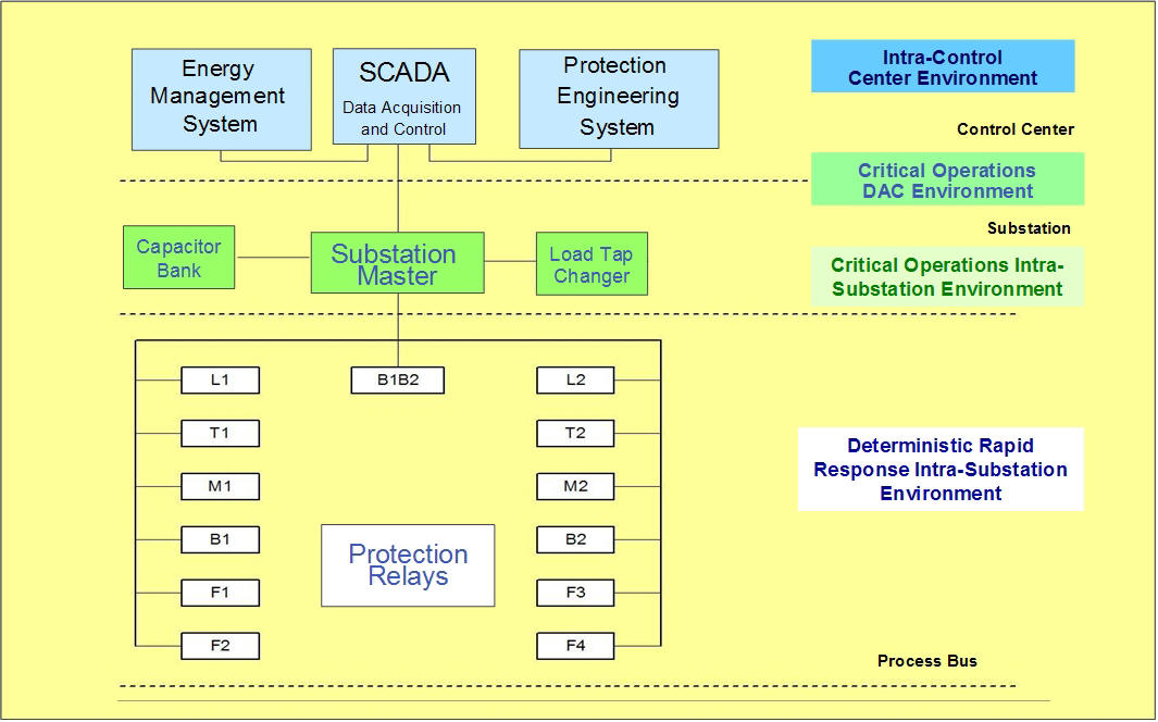
Substation Environments
The following drawing illustrates the two main IntelliGrid Environments
in a Substation, the Environment between a substation and the control
center, and the Environment within a control center. Click on each Environment to see a complete
description of the Environment, the requirements that define the
Environment, and the recommended standards, technologies, and best
practices for that Environment.
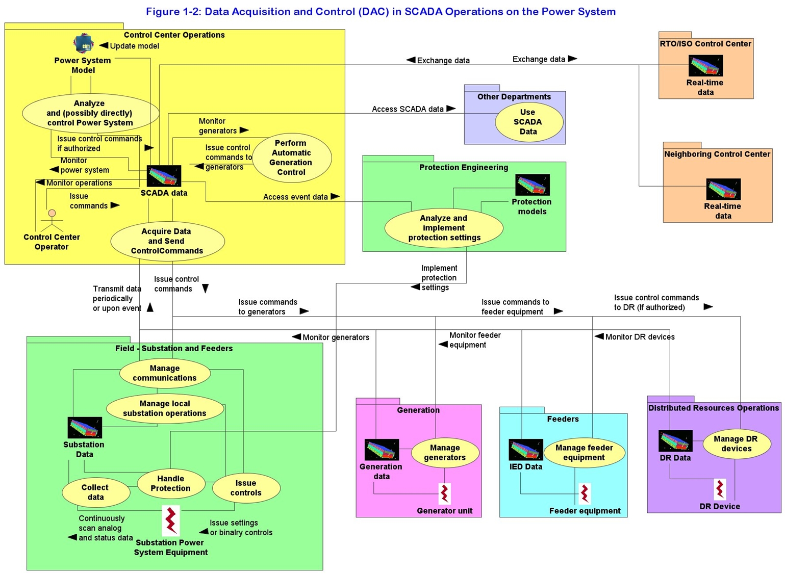
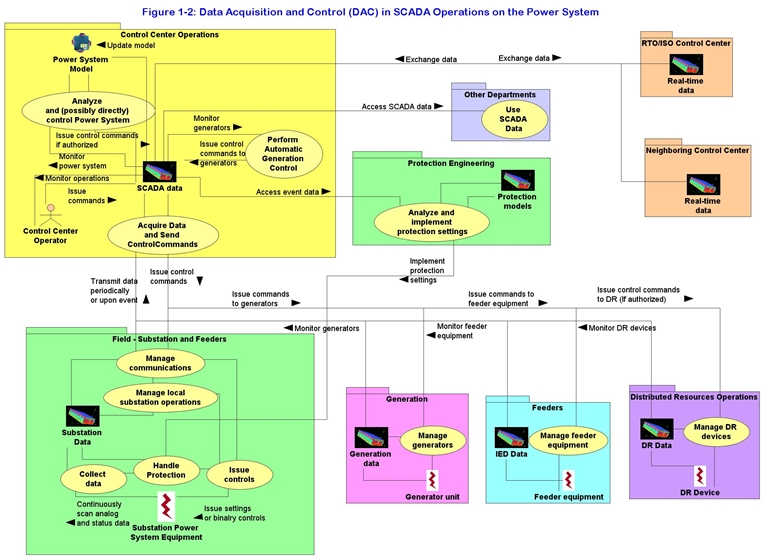
The following figure shows some of the key information flows of
data acquired in substations and other field locations (click on
picture to enlarge it).
Narrative
Sampling and Sensing of Power
System Equipment is
performed by CTs, PTs, sensors, Intelligent Electronic Devices (IEDs), Remote Terminal
Units (RTUs), or other microprocessor-based controllers. Control of
Power System Equipment is performed by controllers, IEDs, or RTUs.
These control commands are sometimes the result of applications within
the IED or controller, and sometimes are passed through from external
systems, such as a Substation Master System or a Control Center SCADA
system.
The
communications links are often very short (a few meters) but can also
entail multi-mile links. The communications media typically are copper
wires or optical fibers, but can include power line carrier,
radio-based media, and possibly other media. Typically, the timing of
the sampling, sensing, and control must meet very
stringent requirements for rapid response (about 4
milliseconds), high availability, and high
security.
They either use internal
applications or are instructed by other entities to issue control
signals to associated power system equipment. For example:
- Digital CTs sample the current on a
substation bus
- Sensors monitor the status of a
circuit breaker
- A Protection IED issues a trip
signal to a circuit breaker
- Load Tap Changer IED raises and lowers the transformer
tap position according to pre-set algorithms, based on voltage levels
sensed by Potential Transformers (PTs).
- A circuit breaker IED issues an electro-mechanical or
solid-state-based trip signal to a circuit breaker.
- A DER IED controller senses status and measurements of a
DER generator and its prime mover, and then issues start and stop
signals.
Diagram
Steps for Sampling, Sensing, and Control of Power System
Equipment
An IED receives
sensor data from a Potential Transformer (PT), or a circuit breaker
IED issues a trip signal to a circuit breaker device.
|
# |
Event |
Name of Process/Activity
|
Description of
Process/Activity |
Information Producer
|
Information
Receiver |
Type of Info Exchanged
|
IntelliGrid Architecture Environment |
|
1.1 |
Continuous or very frequent data retrieval |
Monitor sensors |
IED
performs analog-to-digital and/or
digital-to-digital conversions from
sensor inputs, retrieving data from its
associated power system equipment and
from PT and CT sensors.
IED then
performs basic engineering conversions
on the raw data, processes the
information, and determines if any
subsequent actions are needed based on
limit checking and other process results |
Sensors |
IED |
Raw
sensor data |
Deterministic Rapid
Response intra-substation
environment |
|
1.2 |
Processed data indicates further local action needed |
Send control commands |
IED
issues control commands to power system
equipment, based on the results of
processing the input data from the field |
IED |
Other
IEDs or power system equipment, such as
circuit breakers, voltage regulators,
capacitor bank switches, LTCs,
reclosers, etc |
Signal
data |
Deterministic Rapid
Response intra-substation
environment |
Narrative
Protection IED Interactions are undertaken to respond to a
relatively local situation within a substation or on a feeder that
requires the exchange of information among two or more IEDs,
specifically to determine whether to issue a trip signal, and which equipment
should be tripped.
The communications media are normally
point-to-point cables, LANs (in automated substations), and point-to-multi-point radio channels
(on feeders).
Transmission protection actions require very high
speed communication channels,
with response timeframes of 1 to 4 milliseconds, while distribution
protection actions involving automated switches
could tolerate longer response times. For example:
- A protection IED issues a trip command over a
Process Bus LAN to a circuit breaker IED within a substation, based on its
detection of different power system measurements, such as low
frequency, current overload, etc.
- Multiple automated switch IEDs, using
point-to-multi-point spread spectrum radio communications media,
respond to a fault condition on a feeder segment by opening and
closing switches to isolate the fault and restore power to unaffected
feeder segments.
Diagram
Steps for Protection IED Interactions
A protection IED issues a trip command over a
Deterministic Rapid Response LAN to a circuit breaker IED within a substation, based on
its detection of different power system measurements, such as low
frequency, current overload, etc.
|
# |
Event |
Name of Process/Activity
|
Description of
Process/Activity |
Information Producer
|
Information
Receiver |
Type of Info Exchanged
|
IntelliGrid Architecture Environment |
|
2.1 |
Continuous monitoring |
Sensor monitoring |
Each IED in the group monitors local power system equipment |
Power system equipment |
IEDs |
Sensor data |
Deterministic Rapid
Response intra-substation
environment |
|
2.2 |
Fault in a feeder segment occurs |
Fault detection |
A fault occurs in a transmission segment. This fault is detected
by one or more IEDs, including a
protection IED in the substation.
|
Sensor or IED |
IED |
Fault sensor data |
Deterministic Rapid
Response intra-substation
environment |
|
2.3 |
Protection IED issues trip command |
Trip command |
The protection IED issues a trip command to the
breaker
IED. Using the mechanisms described in
section 2.2.1, the breaker IED issues a
trip command to its breaker. |
Protection IED |
Equipment |
Trip command |
Deterministic Rapid
Response intra-substation
environment |
|
2.4 |
Recloser trips |
Monitor response to command |
The breaker trips and this information is received by
automated switch IEDs on the affected
feeder. |
Sensor or IED |
IED |
Control response sensor data |
Deterministic Rapid
Response intra-substation
environment |
|
2.5 |
IED internal analysis results – multiple iterations |
Local IED response to fault |
IEDs near faulted feeder segment communicate and determine
which switches should be opened and
which closed. This occurs a number of
times, depending upon the results of the
IED actions, the results of the breaker
actions, and the parameter settings in
the IEDs. Each IED performs its actions
via the 2.2.1 process. |
One IED |
Other IEDs |
Digital electric data |
Critical
intra-substation environment |
Narrative
A Substation Master System is a system
within a substation that can:
-
Acquire data from
the substation IEDs
-
Pass selected
data to a control center
-
Receive control
commands from the control center
-
Issue control
commands to IEDs and controllers for
them to take action
Substation Master Systems
can be relatively simple or can include
sophisticated capabilities. They include data
concentrators, Remote Terminal Units (RTUs), as well as more
sophisticated Substation Control and Data
Acquisition Systems. These are generalized systems, as opposed to IEDs or
controllers, and usually monitor and/or control more than one power
system device. Data concentrators and RTUs just pass data through them, acting
primarily as communication nodes, although they may include a local
database. Basic Substation Master Systems may include applications to perform some
local interactions, or may help coordinate IED actions. Highly capable
Substation Master Systems may include applications
that can perform closed loop control (e.g. does not interact with the human
operator before issuing a control command).
The communications media
can be LANs, copper wire, optical cables, microwave radio, leased
telephone lines, cellphones, and many other types. Data exchanges
range from a few 10’s of milliseconds up to 1 second. Examples
include:
- Data concentrator in a substation monitors data from
IEDs that are located on feeders connected to the substation. It
passes some of this data to a SCADA system and passes control commands
from the SCADA to the IEDs. It may collect sequence of events data and
some statistical information in a database.
- Substation master coordinates the protection settings of
substation IEDs based on requests from the SCADA system for different
response patterns. For instance, different protection trigger levels
are set for recloser responses if a storm is pending, or if
reconfiguration of a feeder impacts the expected fault current level,
or if DER generation levels could cause fuses to blow unnecessarily.
- Substation master provides information to automated
switch IEDs on a feeder as to the actual configuration of a
neighboring feeder. This information will permit the automated switch
IEDs to take more appropriate action if a fault occurs.
- Substation master performs
advanced substation automation functions, by responding to field conditions
reported by IEDs and issuing control commands for volt/var
optimization, fault location, isolation, and restoration, multi-feeder
reconfiguration, etc.
Diagram
Steps for Substation Master Systems
Substation master systems coordinate the protection
settings of substation IEDs based on requests from the SCADA system
for different response patterns. For instance, different protection
trigger levels are set for zone 3 protection or for recloser responses if a storm is pending,
or if reconfiguration of a feeder impacts the expected fault current
level, or if DER generation levels could cause fuses to blow
unnecessarily.
|
# |
Event |
Name of Process/Activity
|
Description of
Process/Activity |
Information Producer
|
Information
Receiver |
Type of Info Exchanged
|
IntelliGrid Architecture Environment |
|
3.1 |
On-going monitoring of data by substation master |
Data monitoring |
Substation master receives digital data from IEDs within a
substation and along adjacent feeders.
This data can be transmitted
periodically or upon significant change
of an analog value or upon status change |
Multiple IEDs |
Substation master |
Digital electric data |
Critical intra-substation
environment |
|
3.2 |
Request by SCADA to change protection settings |
Change settings |
As requested by the control center SCADA system, the
substation master determines the
appropriate settings for protective
relays and reclosers for a specific
scenario (e.g. storm, changed feeder
configuration) |
Substation master |
Protection and recloser IEDs
|
Settings |
Critical Operations
DAC |
|
3.3 |
Power system event with IEDs responding |
Sequence of events recording |
A power system event occurs, to which the local IEDs
respond. They then report their sequence
of events to the substation master for
inclusion with disturbance records. |
IEDs |
Substation master |
IED SOE |
Critical Operations
DAC |
|
3.4 |
Operator initiates trip of breaker |
Select before operate (SBO) command |
The substation master ensures that a control request from
the control center is authorized, then
passes the request to the circuit
breaker IED for execution |
Substation master |
Circuit breaker IED |
SBO control request |
Critical Operations
DAC |
Narrative
DER management systems perform
monitoring and control of a DER device, either at a customer site or
within a substation or from a utility's distribution control center (see
Figure 1‑1). The DER
management system could be a DER owner’s SCADA system, a customer’s
Building Automation System (BAS), an energy aggregator’s system, or a
distribution operations SCADA system. Communications media can include virtually any type, so long
as response times of a few seconds can be accommodated. Examples
include:
·
Loss of power is detected at a customer site. The backup
diesel generator starts up, the automatic transfer switch connecting
the customer to the utility EPS opens, and the generator is connected
to the customer’s local EPS (or just the critical equipment).
·
The owner of the DER device decides to reduce his load
on the utility EPS by increasing generation. The DER operator
implements this decision by setting new parameters in the DER
management system. (These are manual actions by
persons.) As an automated result, another generator is started by
the DER management system, synchronized with the local EPS, and
interconnected.
·
An energy aggregator sets groups of DER devices to cycle
on and off over the next day, taking into account pollution limits,
the real-time price of energy, and contractual arrangements with the
owners of the DER devices.
·
While a DER device is interconnected with the utility
EPS, a fault occurs on the feeder. The DER management system ensures
that the DER device either trips off or the interconnection circuit
breaker opens.
·
The DER management system collects sequence-of-events,
performance data, and statistical information from DER devices in a
substation.
Diagram
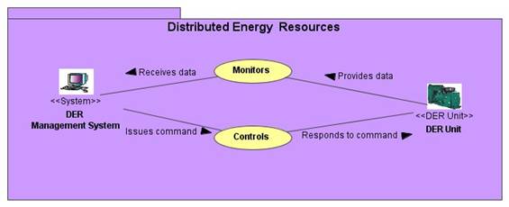
Figure DER Management Systems Monitoring and Control of DER
Devices
Steps for DER Management System Monitoring and Control of DER
Devices
The owner of the DER device decides to reduce
his load on the utility EPS by increasing generation. The DER operator
implements this decision by setting new parameters in the DER
management system. (These are manual actions by persons.) As an
automated result, another generator is started by the DER management
system, synchronized with the local EPS, and interconnected.
|
# |
Event |
Name of Process/Activity
|
Description of
Process/Activity |
Information Producer
|
Information
Receiver |
Type of Info Exchanged
|
IntelliGrid Architecture Environment |
|
4.1 |
DER owner decides to reduce load |
Owner decision |
DER owner contacts (calls, e-mails, alarms) DER Operator
that additional energy from DER
generation is needed. |
DER owner |
DER Operator |
Call by person |
Call – Outside Scope of IECSA |
|
4.2 |
DER operator enters new parameters |
Establish parameters |
DER Operator sets new parameters for DER generation output
in the DER management system. |
DER Operator |
DER Management system |
DER data entry |
User interface (Outside scope of IntelliGrid Architecture) |
|
4.3 |
Start command |
Start DER |
DER management system issues start command to a DER unit. |
DER management system |
DER unit |
DER start-up command |
DER Monitoring and Control |
|
4.4 |
DER Unit started |
Synchronization |
DER Unit starts and synchronizes with the Local EPS, and
reports success and current operating
measurements to DER management system |
DER unit |
DER management system |
DER reporting |
DER
Monitoring and Control |
|
4.5 |
On-going DER unit operations |
Monitoring DER |
DER unit reports current operating measurements to DER
management system for operational
information as well as historical and
statistical information |
DER unit |
DER management system |
DER historical and statistical records |
DER
Monitoring and Control |
|
4.6 |
Environmental limit reached
|
Environmental limit |
DER management system calculates that a diesel generator has
reached its daily (assigned) limit of
emissions, and issues a stop command |
DER management system |
DER unit |
DER stop command |
DER
Monitoring and Control |
|
4.7 |
DER unit stops |
Stop DER |
DER unit stops and shuts down. It reports back to the DER
management system with its latest data |
DER unit |
DER management system |
DER reporting |
DER
Monitoring and Control |
|
4.8 |
DER unit reports received |
DER reports |
DER management system provides DER unit data to DER operator
via a User Interface |
DER management system |
DER operator |
User display |
User
interface (Outside scope of IntelliGrid Architecture) |
Narrative
SCADA systems perform remote monitoring
and control of field equipment and IEDs.
The term “SCADA” is used here to imply any centralized system which
retrieves data from remote sites and may issue control commands when
authorized. These SCADA systems are typically located in a utility
control center, but may include an engineering “SCADA” system which
retrieves protection data or disturbance data, or a maintenance
“SCADA” system which monitors the health of both power system and
communications equipment.
SCADA system monitoring can use communication
channels directly to IEDs, via Remote Terminal Units (RTUs), through a
data concentrator, through a substation master, or through a DER
management system. The communications media can include virtually any
type, so long as response times of 1 second can be accommodated.
Although typically seen as used only for real-time distribution
operations, the data acquired by the SCADA system can be used by many
different systems, applications, and personnel in the control center.
This Use Case is limited to the monitoring and control function by
SCADA systems; other Use Cases (e.g. ADA Use Case) describe their
interactions with the SCADA systems.
SCADA system monitoring and control examples
include:
·
Power system operations SCADA system receives real-time
data from power system equipment via:
– RTUs
– IEDs
inside substations
– IEDs
along feeders
–
Substation masters
– DER
(or other generation) management systems
– Other
control centers
–
Manual entry
·
Power system operations SCADA system issues control
commands to power system equipment in real-time via:
– RTUs
– IEDs
inside substations
– IEDs
along feeders
–
Substation masters
– DER
(or other generation) management systems
– Other
control centers (if authorized)
·
Power system operations SCADA system receives metering
information
·
Data management “SCADA” system receives power equipment
configuration data from devices. It may have its own communication
channels to the remote sites, or it may acquire this data through the
distribution operations SCADA system
·
Engineering “SCADA” system receives sequence of events
data, oscillographic data (special handling required), historical
data, and statistical data. It may have its own communication channels
to the remote sites, or it may acquire this data through the
distribution operations SCADA system
·
Maintenance “SCADA” system receives data related to the
health of power system equipment and communications equipment. It may
have its own communication channels to the remote sites, or it may
acquire this data through the distribution operations SCADA system.
·
Planning “SCADA” system receives data that can be used
for statistical analysis of power system measurements: maximums,
minimums, averages, trends, profiles, power quality metrics, etc,
needed for short and long term planning.
Diagram
Steps for Monitoring and Control by SCADA System
Distribution operations SCADA system monitors
and controls power system equipment via a multitude of mechanisms.
|
# |
Event |
Name of Process/Activity
|
Description of
Process/Activity |
Information Producer
|
Information
Receiver |
Type of Info Exchanged
|
IntelliGrid Architecture Environment |
|
5.1 |
Establish an association between SCADA and RTU and/or IED |
Establish association |
Using an interactive process between an RTU or IED and a
SCADA system, an association is
established. This interactive process
varies from protocol to protocol, but
essentially entails setting up what data
is available and what data is to be sent
under what conditions. In some
protocols, many of the steps are manual,
while in others they are almost entirely
automatic. |
SCADA and RTU/IED |
RTU/IED and SCADA |
Association |
Critical Operations
DAC |
|
5.2 |
Status change occurs in power equipment |
Detect status change |
A status change occurs in some power system equipment. This
status change is “immediately” sent
(usually within 1 second) to the SCADA
system. Depending upon the
communication “services”, the status
value can be sent periodically, or can
use the “report-by-exception” service,
which sends a status value only if it
changes |
IED which is sensing power system equipment |
SCADA system |
Status change |
Critical Operations
DAC |
|
5.3 |
“Significant” change in a measurement value |
Detect significant measurement change |
A significant change occurs in a measured value. (Significant
implies it exceeds some pre-established
limit.) This changed value is sent
according to pre-established protocol
services: e.g. report-by-exception
sends it immediately (within 1 to 2
seconds), while periodically
sends it when the time period elapses.
The protocol also determines what information is included,
such as timestamp, quality code, etc. |
RTU which is sensing power system equipment
|
SCADA system |
Measurement change |
Critical Operations
DAC |
|
5.4 |
SCADA issues control command |
Issue control command |
Either an operator or an application issues a control command
through the SCADA system to an RTU or
IED. These control commands are
typically immediately implemented by
sending a signal to the power system
equipment |
SCADA |
RTU or IED which initiates signals to power system equipment |
Control command |
Critical Operations
DAC |
|
5.5 |
SCADA sends parameter settings |
Set parameters |
Either an operator or an application sends a parameter
setting through the SCADA system to an
RTU or IED. These parameter settings may
be stored for later use or may be used
immediately to initiate a signal to the
power system equipment, such as a raise
or lower control command |
SCADA |
RTU or IED |
Parameter setting |
Critical Operations
DAC |
|
5.6 |
SCADA requests specific data |
Request data |
Either an operator or an application requests specific data
to be sent to the SCADA system from an
RTU or IED. |
SCADA |
RTU or IED |
Request |
Critical Operations
DAC |
|
5.7 |
Sequence of Events log |
Transmit sequence of events records |
An RTU or IED has collected Sequence of Events log and
initiates its transmittal to the SCADA
system |
RTU or IED |
SCADA |
SCADA SOE |
Critical Operations
DAC |