The objective of the Self-Healing Grid (SHG)
applications is to evaluate power system behavior in real-time,
prepare the power system for withstanding credible combinations of
contingencies, prevent wide-area blackouts, and accommodate fast
recovery from emergency state to normal state.
Description
The SHG function comprises a set of computing
applications for information gathering, modeling, decision-making, and
controlling actions. These applications reside in central and/or in
widely distributed systems, such as relay protection, remedial
automation schemes (RAS), local controllers, and other distributed
intelligence systems. All these applications and system components
operate in a coordinated manner and are adaptive to the actual
situations.
The conventional methodology for emergency
control is based on off-line studies for selection of the local
emergency automation schemes, their locations, and their settings.
Such off-line studies are usually performed for selected operating
conditions based on typical cases and on previous emergencies.
However, the design of remedial actions and emergency automation
schemes based on previous emergencies may be ineffective for the
future emergencies. In reality, the emergency situations often occur
under conditions that are quite different from the study cases. With
the advent of deregulation, the energy schedules are derived from
financial considerations rather than strictly power operations
considerations. Therefore, the types of possible contingencies
increase substantially, and it would be very difficult to study with
purely off-line analyses. Not only are there increased pressures from
deregulation, there are new challenges imposed by the involvement of
distribution systems and customers in preventing and responding to
power system emergencies. For instance, with the increased number of
distributed energy resource (DER) devices connected to the
distribution system, distribution operations have to expand to monitor
and manage (if not actually control) these DER devices. The advances
of Distribution Management Systems (DMS) and Advanced Distribution
Automation (ADA) make these systems available for real-time
coordination of transmission and distribution operations in normal,
emergency, and restorative states of the power systems.
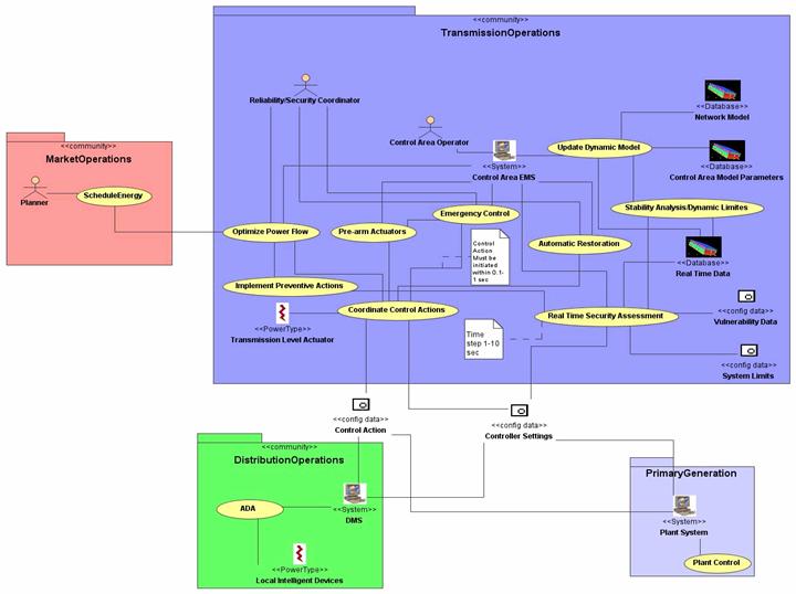
The SHG will be supported by fast data
acquisition systems (Wide Area Measurement Systems and SCADA) and will
include fast simulation and decision-making applications observing
wide power system areas. These wide-area applications will coordinate
the behavior of distributed control systems (regional EMS, DMS, Plant
EMS, RAS, and relay protection). These distributed systems and
actuators will perform adequately fast under emergency and later under
restorative conditions following the rules and settings preset by the
upper level simulation and decision-making applications. The
coordination of different systems and actuators will be accomplished
in a hierarchical manner. Some directive from the upper level, e.g.,
from the ISO/RTO EMS will be transmitted to the regional EMS, and some
commands and settings will be downloaded directly to the actuators.
The regional EMS will transmit some directives to the DMS and plant
EMS and some commands and settings will be directly downloaded to the
actuators, which are in the corresponding areas of responsibility.
Some local actuators will be integrated into distributed intelligence
schemes and will communicate among themselves in a peer-to-peer
manner. The rules of behavior of the distributed intelligence schemes
can be preset by the upper control system. (See Fig.1).
The power system operators will be the Persons In
Charge (PIC) for the performance of the entire SHG and will
participate in the system setup and decision-making processes, which
allow sufficient time for the operators to perform an educated action.
Under emergency conditions, when fast and complex actions should be
performed, the pre-armed and adaptive local and distributed
applications and automatic schemes should be the main executors for
the protection of equipment and prevention of blackouts.
The future control system for the self-healing
grid will differ from the current approaches by implementing
significantly more automated controls instead of supervisory controls
by the operators and by aiming at preservation of adequate integrity
of the generation-transmission-distribution-customer system instead of
self-protection of equipment only.
Figure SEQ Figure \* ARABIC 1 Integration of DMS/ADA with EMS - A
real time adaptive decision -making and wide area control system is
required to meet the objectives of the self-healing grid.
Gather the network model parameters in
real time, including actual data about
the mode of operation and settings of
the automated systems and devices.
SCADA System
Energy Management System
Control Area Network Model Parameters
High amount of data need to be handled.
Common data format is an issue. Missing
data is another issue. The data exchange
could be report- by-change.
Synchronization of data is an issue
Synchronizes and estimates the data
obtained from SCADA and Wide Area
Measurement Systems, identifies and
corrects inaccurate data, replaces bad
and missing data. Incorporates updates
of parameters of controllers and control
systems and outputs from other automated
systems (Distribution Management System,
ADA, plant EMS, neighbor area, ISO/ RTO
EMS, MOS).
Regional System Operator
Regional System Operator
Regional System Operator through State
estimation/ Dynamic Model Update
Application.
The calculation and updates should be
complete within 1 second in some cases
Simulates the reactions of relevant
automated systems based on the updated
system model.
Energy Management System
Energy Management System
Boundary Conditions
In order to achieve timely results, the
system configuration should be
considered. Whether to conduct the
simulation in centralized or distributed
fashion will have significant impact on
the architecture.
Impose the inhibition of control, if the
analysis of hypothetical controller
failure would yield much more severe
consequences than the denial of the
control action itself.
Coordinate the corrective actions based
on acceptable supply-demand balance in
prospective islands, weak links between
control areas, within control areas, and
within islands, contractual agreements
and market rules for implementation.
Regional System Operator
Power Marketer, Energy Management System
Control Actions
Bi-directional communications among
Power Marketer, Regional System Operator
and control area EMS.
Start reserve/tripped generation,
control shunts and analyze the
conditions for load restoration, based
on generation reserves, reactive power
support, and transmission transfer
capacity.
Regional System Operator
Energy Management System
System restorations based on system
restoration plans prepared (authorized)
by operation management
Organizations responsible for maintaining
transmission system reliability and ensuring open
access to the grid for all market participants.
Regional System Operator responsibilities include:
transmission planning, contingency analysis,
real-time system operation, and market monitoring
and management.
SCADA System
System
Control area supervisory control and data
acquisition system
Energy Management System
System
Control area energy management system
Wide Area Measurement System(s)
System
Phasor measurement system covers a wide power
system area.
Power Marketer
Entity
Entities who buy and sell electricity in wholesale
markets.
PowerSystem
System
Composition of interconnected transmission,
generation, distribution power systems
Reliability/security Coordinator
Entity
Entities that are responsible for the reliability
of the power grid and have the authority to
fulfill that responsibility within the operating
region managed by an Regional System Operator
ControlAreaOperator
Entity
Entities that manually operate and maintain
control area facilities and equipment, and execute
control orders.
Transmission Level Actuator
System
Power system actuators, which are controlled
directly by transmission control area SCADA/EMS
Distribution and Plant Control System
System
Distribution management systems, distributed
energy resources and generation plant control
systems
IED
Device
Intelligent electronic devices including
protective relays, RTUs, sensors.
Grouping (Community)
Group Description
Transmission Level Actuator
Power system actuators, which are controlled
directly by transmission control area
SCADA/EMS
Actor Name
Actor Type (person, device, system etc.)
Actor Description
FACTS Device
System
A
power electronic based system and other static
equipment (such as Static Var Compensator,
Thyristor Controlled Series Compensator, STATCOM)
that provide control of one or more ac
transmission system parameters to enhance
controllability and increase power transfer
capability.
RAS
Systems/devices
Local or distributed intelligence remedial action
schemes acting under emergency operating
conditions in accordance with either pre-set or
adaptive settings to protect equipment, prevent
wide-area blackouts, and restore services.
Grouping (Community)
Group Description
Distribution and Plant Control System
Distribution management systems, distributed
energy resources and generation plant
control systems.
Actor Name
Actor Type (person, device, system etc.)
Actor Description
Distribution Management System
System
A
distribution management system is a suite of
application software that supports distribution
system operations.
ADA
System
Advanced distribution automation is a
multifunctional system that supports remote
monitoring, coordination and operation of
distribution components by taking full advantage
of new capabilities in power electronics,
information technology and system simulation.
DER Device
Device/System
Distributed energy resource refers to distributed
generation, storage, load management, combined
heat and power and other sources involved in
electricity supply, both in stand-alone and
interconnection applications.
Plant Control System
System
A
DCS (distributed control system) that operates a
generation plant
Grouping (Community)
Group Description
IED
Intelligent electronic devices including
protective relays, RTUs, sensors.
Actor Name
Actor Type (person, device, system etc.)
Actor Description
Protective Relay
Device
A
device that responds to faults by tripping a
breaker according to control logic, based on the
monitoring of current and voltage values, and on
communications with other protective relays.
Phasor Measurement Unit
Device
Phasor Measurement Unit – a generic device which
produces synchronized phasors from voltage and/or
current inputs and synchronizing signals.
Remote Terminal Unit
Device
Remote Terminal Unit – A device used to
control/monitor/record sensor results in SCADA
applications
Information exchanged
Information Object Name
Information Object Description
Real Time Data
Information needed to be updated or exchanged in
real time. These data include voltage, current
phasor measurements, and frequency, rate of change
of frequency, rate of change of voltage
calculations. The system flow (both MW and MVAR)
can be derived by the voltage and current phasors.
Control Area Network Model
One could partition the power system network model
used by a control area into four subnetworks as
follows: [1]
Subnetwork 1. Internal transmission network is
modeled in detail and it is monitored.
Subnetwork 2. Unmonitored internal transmission
network is modeled in detail as well. It is
expected that the unmonitored internal network
will be minimized in time given the growth in the
utility communication infrastructure.
Subnetwork 3. Adjacent external network is modeled
in detail because it has significant impact on the
security of the internal system. This model will
be updated based on the input from adjacent
control center.
Subnetwork 4: Distant external network is modeled
by reduced equivalents because it has less impact
on the internal system.
Control Area Network Model Parameters
The parameters in the control area network model
include facility status (such as generation shifts
due to changes in transaction schedules,
redispatch and unit outages, and the status of
power plant auxiliary equipments), transmission
element impedances, control device set points
(such as generator and LTC settings), generation
response capabilities (MW/min), breaker/switch
states (these states are critical to update the
topology of the control area network), and bus
load.
Controller Settings
These settings include relay protection and load
shedding schemes, other remedial action schemes
(RAS), and set points for FACTSDevice devices,
voltage controller, phase-shifters and other
controllers.
Control Actions
The control actions involve real and reactive
power generators, controllable shunts in
transmission, FACTSDevice devices, phase shifters,
Load Tap Changers (LTCs), transmission
sectionalizing, and distribution automation
functions like Volt/Var control, feeder
reconfiguration, and load management functions.
Transmission System Limits
The transmission system limits include the
determination of the thermal limits, available
capacity, economic constraints, interface limits,
steady state, transient and small signal voltage
stability limits.
PowerSystem Vulnerability Data
The power system vulnerability data include fault
information, environmental data, and other sources
of power system vulnerability data
Boundary Conditions
Refer to the power system conditions such as
voltage, current, and phase angles at the boundary
of the network model that is used to simulate
internal system behavior.
Activities/Services
Activity/Service Name
Activities/Services Provided
Dynamic Model Update
EMS system performs dynamic model update, state
estimation, bus load forecast. Dynamic Model
Update sub-function updates the system model to
reflect the status of the transmission and
generation equipment and critical operational
parameters in real-time, based on gathering the
wide-area synchronized phasor measurements and
estimating the missing and inaccurate data; The
bus-load model update and forecast is supported by
the distribution operation model and analysis; In
a multi-area interconnected system, each control
area updates its model and exchanges the full or
reduced model with neighbor areas.
Optimal Power Flow (OPF)
EMS system performs optimal power flow analysis,
recommends optimization actions: Optimal Power
flow provides operations personnel with
recommended system changes to correct limit
violations while optimizing the system for
pre-defined objectives including minimizing
losses, maximizing MW capacity via optimal Mvar
control, minimizing the number of controls moved,
or minimizing the movement in all available
controls. OPF uses bus load models supported by
Distribution Management System applications and
includes the bus dispatchable load in its
variables. OPF issues sets of actions for multiple
local controllers, distributed intelligence
schemes, and Distribution Management System
applications.
Stability Analyses
EMS system performs stability study of network to:
Determine the dynamic stability limits and
Determine whether network is operating close to
limits of stability
Real Time Contingency Analysis
EMS system performs contingency analysis (CA),
recommends preventive and corrective actions:
Contingency Analysis and post-contingency analysis
of remedial action provides the ability to correct
problems caused by harmful disturbances
Result from contingency analysis is analyzed by
post contingency optimal power flow
The post contingency optimal power flow simulates
the behavior of relay protection, load shedding
schemes, other remedial action schemes (RAS),
FACTS devices, voltage controllers,
phase-shifters, and other local controllers.
Status and set points are obtained from the
dynamic model update, and are applied to
probabilistic models of power system operations.
CA sub- function considers multiple sets of
independent and dependent contingencies and
provides risk assessment and severity evaluation
of the sets
CA sub-function develops and implements preventive
actions to reduce the risk and severity of
anticipated contingencies, including
generation-constrained optimal power flow
implemented in closed-loop mode, blocking of some
controls, and pre-arming of RAS and other
distributed intelligence schemes.
CA checks the success of execution of the
preventive actions and changes the input criteria
in case of failure.
This activity is further elaborated in the
“Contingency Analysis” use cases.
Automatically sheds load under conditions of low
frequency, based on pre-defined or real-time
computed settings, modes of operations, and
priorities of connected groups of customers.
Should be made adaptive to the conditions of the
interconnected self-healing grid and
non-intentional and intentional islanding.
Automatically sheds or reduces generation to
preserve load balance over the transmission lines
and power system stability
Automatically sheds load under conditions of low
voltage, based on pre-defined or real-time
computed settings, modes of operations, and
priorities of connected groups of customers.
Should be made adaptive to the conditions of the
interconnected self-healing grid and
non-intentional and intentional islanding.
Automatically sheds load under specific
conditions, based on pre-defined or real-time
computed settings, modes of operations, and
priorities of connected groups of customers.
Should be made adaptive to the conditions of the
interconnected self-healing grid and
non-intentional and intentional islanding.
Restores load based on real-time power system
restoration capabilities. Should be made adaptive
to the changing conditions.
Fast control of LTC to prevent voltage instability
(Fast = 10 to 100ms – depending on the size of the
control area)
Fast control of shunts to prevent voltage
instability
Fast control of series compensation devices to
prevent system instability and critical overloads
Balanced separation of the power system into near
balanced islands to prevent cascading development
of severe contingencies into wide-area blackout.
Filters and summarizes multiple alarms into a
conclusive message about the core cause of the
contingency. Uses centralized alarm reduction
based on events from multiple substations
Automatically locates faults based on high-speed
synchronized measurements
Provides field crews with real-time information by
using mobile computing
Provides pre-fault, fault, and post-fault data for
fault location, alarm processing, and analyses of
the emergency operating conditions.
Provides other EMS applications and the operators
with near-real time stability limits
Changes the modes of operation, the settings, and
the priorities of RAS, based on evaluation of the
developing or expected emergency conditions.
Issues summary requirements to DISCOs for changing
distribution operations, based on evaluation of
the developing or expected emergency conditions.
Changes the modes of operation, the objectives,
constraints, and the priorities of Distribution
Management System Volt/var control application,
based on evaluation of the developing or expected
emergency conditions
Changes the modes of operation, the objectives,
constraints, and the priorities of Distribution
Management System feeder reconfiguration
application, based on evaluation of the developing
or expected emergency conditions
Issues summary requirements (amount and timing) to
DISCOs for activating the
interruptible/curtailable load systems. DISCO
defines the specifics of implementation.
Issues summary requirements (amount and timing) to
DISCOs for activating the direct load control
systems. DISCO defines the specifics of
implementation.
Issues summary requirements (amount and timing) to
DISCOs for activating the DER Device reserves.
DISCO defines the specifics of implementation.
Issues summary requirements (amount and timing) to
DISCOs for activating the load managements
systems. DISCO defines the specifics of
implementation.
This activity is further elaborated in the
“Emergency Operation” use cases.
System Restoration
Operators perform system restorations based on
system restoration plans prepared (authorized) by
operation management. System restoration to normal
state, in addition to automatic restoration, if
needed.
Unit starts, auto-synchronization, load
energization, based on the power system recovery
capability monitored and coordinated by EMS
This activity is further elaborated in the
“Advanced Auto Restoration” use case.