Many Energy Service Providers and Market
Operators administer customer side Demand Response and Load Control
programs to ensure grid stability and stable operation during times of
peak demand or system emergencies arising from generator outages or
transmission and/or distribution constraints. With some programs, the
customer – either residential or commercial - reduces the required
load upon instruction from the Energy Service Provider or Market
Operator. With other programs, the Energy Service Provider, Market
Operator, or a Curtailment Service Provider remotely reduces the
load. Some of these programs are conducted on a voluntary basis,
where the customer can opt to maintain the level or load, or
mandatory, where the customer either will be dropped off the system or
will incur significant financial penalties for noncompliance. The
customer may or may not realize benefits from the program, such as
discounted rates. Some programs may be mandated to enable the Energy
Service Provider to provide electric service to the customer in areas
where there are transmission or distribution constraints. This
function focuses on Demand Response/Consumer Load Control that is non
responsive to price – pricing signals are not sent to the customer.
Communication systems play a key role in this function as in the
consumer control load configuration, instructions must be sent to the
customer to reduce or eliminate load and verification of
compliance/noncompliance must be obtained by the Energy Service
Provider or Market Operator. In the configuration where the Energy
Service Provider, Market Operator, or CSP controls the load, commands
must be sent to equipment at the customer site that will cycle down or
cease operation. Verification of successful action must also be
obtained.
Day-in-the-Life
A
typical day-in-the-life scenario is as follows (note that the
discussion is marked up with numbers that are used later in the
analysis to derive requirements from the scenario):
Utilities with significant periods of peak
demand often establish and administer demand response/load control
program where residential and commercial customers may, in exchange
for discounted rates, agree to, on a voluntary or mandatory basis,
reduce or cycle down load. Utilities, especially those with a
customer base operating significant cooling and/or electric heating
loads – primarily heat pumps, and electric water heating loads, are
implementing programs centered around these loads to address periods
of peak demand – extremely hot or cold days or times of system
emergency – where a generator may be removed from service for
maintenance or where the transmission and/or distribution system may
be constrained. These utilities operate in markets where customer
participation in Real Time Pricing programs has not been authorized by
the state regulatory body or implemented by the utility.
Inside this program, residential and commercial
customers sign up for a program where they receive discounted rates
for participation. The customer may choose to opt out of
participating in a particular instance, but will be compelled to pay a
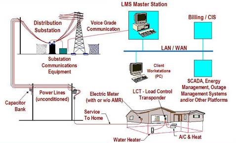
peak demand penalty for nonparticipation. The utility installs
equipment at the customer meter to receive commands from the utility
system operator. These commands operate a load control transponder,
which either interfaces with the thermostat controlling air
conditioning/heating equipment or operates a breaker closing the
circuit powering water heaters and/or pool pumps.
(1)At the onset of a day where the
weather is forecast to be extremely hot or cold or when it is known
the possibility exists for a system emergency, the System Modeler runs
models to determine where and when times of peak demand will occur.
This modeling involves clearly defined parameters such as weather,
tracked seasonal load, load availability factors, and customer load
served by the transmission and/or distribution system. It is
determined that with the available amount of bulk power and the system
experiencing some transmission constraints due to maintenance issues
or locations of some loads in relation to the infrastructure, that a
peak demand event will occur requiring reduction of a certain amount
of customer load.
(2)Under normal operating
conditions, the utility provides two hours’ notice to customer account
representatives and customer service representatives that load
reduction is required and will occur. In a system emergency where a
generator trips offline or lightning or some other event causes the
transmission and/or distribution infrastructure to be overloaded or
unavailable, fifteen minutes’ notice is provided. Other utility
personnel are alerted.
(3)When the peak demand period is
about to begin or when the system emergency occurs, the utility
control center sends a command via the utility’s internal frame relay
system to the distribution substations, where a substation controller
sends a command via Power Line Communication (PLC) to a Load Control
Transponder (LCT). The system operator can target individual
substations to address the amount of load reduction required and the
operational situation of the utility system.
(4)Commands are broadcast out to the
substation controllers, which then broadcast to all LCTs connected to
it. The load control commands are sent out in staggered fashion to
manage information flow across the utility system. “Thermostat
Setback,” “Turn Off,” “Turn On” and “Check Transponder Health” are the
commands sent out. The transponder has an internal counter that counts
the off/on commands and whether the relays were successfully opened.
At the onset of the program, the utility downloaded data from the
counters to determine system health and to validate the models used to
predict system operation, peak demand, and needed load reduction. The
utility has since abandoned this, preferring to rely on automated,
staggered interrogation of the transponders to verify transponder
health. This interrogation does not involve any turning the relays on
or off.
(5)The relays control thermostats,
water heaters, and swimming pool pumps. This customer equipment is
located at both residential and commercial locations and was selected
for its predicted load patterns and ease of remote control. Customers
can choose to override the transponder, but will pay a peak demand
penalty if they do so.
(6)The utility verifies customer
participation via acknowledgement of a successful “Turn Off” command.
After each instance of load reduction, the utility conducts an
assessment of how many MW of load was reduced and uses this
information, along with a review of the command logs and receipt of
successful “Turn On” and Turn Off” commands to refine the model used
to ascertain when the load control programs needs to be activated, how
it needs to be implemented across the service territory, and operating
condition of the communications and control equipment.
Energy Service Provider initiates daily analysis of scheduled
load versus available capacity
Load forecast
Weather forecast
Load availability
Forecast power system conditions for that day. Analyze
forecast temperature conditions against generation
availability, transmission and distribution system
conditions, and historical load patterns
Energy Service Provider sends out notification for Customer
Account/ Service Representatives
Notification
Energy Service Provider issues automatic notification to
Customer Service Representatives, who, depending
on circumstances, receive either two hours’ notice
or 15 minutes’ notice
If it is determined that
customer overrode LCT, then a demand
penalty is assessed against the
customer. Information on this event, as
well as any malfunctions, is factored
into system modeling
High-level actors
who have significant stake on the Demand
Response/Load Management function.
Actor Role Name
Actor Type (person, device, system etc.)
Role Description
Energy Service
Provider
organization
Responsible for
day to day operation of the demand response/load
control program
Public Utility
Commission
organization
Supervises
implementation of demand response/load control
program with direct oversight of rates and
penalties
Customer
Information System
Server
Stores information
about customers participating in the program with
details on participating history, loads to be
controlled, and whether customer has previously
negotiated to opt out of program in certain
situation. Also contains customer billing data
including any demand penalties and rate scheduled
System Demand
Modeler
System
Conducts daily
modeling to determine whether demand response/load
control is required. Contains databases on
weather conditions, generation availability,
transmission and distribution system constraints,
load availability, predicted control patterns, and
details on performance of individual substation
control units and load control transponders
System Modeler
Person
Operates system
demand modeling capability and lets control room
personnel and customer service personnel know
whether load control will be needed according to
the model.
Control Room
Operator
Person
Individual
responsible for activation of automated load
control notification and implementation
Notification and
Control System
System
Upon receipt of
command from control room operator, sends either 2
hour notification or 15 minute notification and
then sends commands out to substation control
units
Customer
Account/Service Representative
Person
Receives
notification from system that load control is
needed and/or imminent and handles calls from
customers about situation - may in time be able to
provide notification to key or sensitive customers
Substation
Controller
Device
Receives commands
from control center and sends commands out to load
control transponders to either cycle thermostats
or shut off water heaters and pool pumps
Load Control
Transponder
Device
Upon receipt from
substation control unit, either transmits command
to thermostat or to water heater or pool pump.
Sends notification of successful or unsuccessful
execution of command back to substation control
unit
Remotely-Controlled Thermostat Device
Device
Upon receipt of
command from Load Control Transponder, cycles
space cooling or heating down or off
Remotely
Controller Circuit Breaker Device
Device
Upon receipt of
command from Load Control Transponder, shuts off
power to water heater and/or pool pump
Frame Relay
Network
System
Carries load
control commands from control room to substation
control unit
Transmission
System Operator
System
Provides power
system configuration and real-time data to system
demand modeler
Transmission
System
Power equipment
Transmission power
system equipment
Transmission SCADA
System
System
System that
provides forecast and real-time transmission
information to the system demand modeler and
control room operator
Distribution
Management System
System
Provides real-time
data to the system demand modeler and control room
operator
Distribution
System
Power equipment
Distribution power
system equipment
SCADA System
System
System that
monitors load control as well as providing
forecast and real-time distribution information to
the system demand modeler and control room
operator
Meter Device
Devices
Collects energy
and demand data per time period
Customer
Person
Agrees to
participate in program. May or may not at time of
system operation choose whether or not to
participate
IT Personnel
Person
Oversees operation
of frame relay network and powerline
communications system
Energy
Schedule Database submitted to the Utility Control
Center and System Modeling
Weather Forecast
Data
Information on
forecast temperatures – especially high and low
temperatures
Generation Outage
and Constraint Data
Data
containing transmission outage and constraint
information
Transmission
Outage and Constraint Data
Data
containing transmission outage and constraint
information
Distribution
Outage and Constraint Data
Data
containing distribution outage and constraint
information
Historical load
data
Data
containing load levels for similar seasonal
parameters – actual demand; temperature;
generation, transmission, and distribution system
availability
Customer
Participation Schedule
Tables of
customers agreeing to participate in the load
control program classified by geographic location
(by substation providing control)
Load Schedule
Schedule
for Customer Load equipment: turning on and off,
cycling, and/or level of load
Customer Load
Forecasts
Forecasts
of individual customer load that can be controlled
Aggregated
Customer Loads
Forecasts of
aggregated customer load that can be controlled –
broken down by geographical location and
substation
Loads Forecast
Load forecasts,
based on different inputs and possible operating
scenarios
Generation System
Data
Generation data,
including scheduled outages, operating
constraints, and real-time information
Transmission
System Data
Transmission power
system data, including scheduled outages,
transmission constraints, and real-time
information
Distribution
System Data
Distribution power
system data, including scheduled outages,
distribution constraints, and real-time
information
Real-time
Monitoring and Control Data
Status, settings,
curtailable load requirements, automated on/off
commands, automated settings, responses back from
substation control units and load control
transponders
Real-time Power
Systems Operations Data
Loads, generation,
A/S, etc.
Meter Data
Energy and demand
data per time period
Customer
Compliance Data
Any peak demand
charges for customers not complying with
participation requirements
Activities/Services
Activity/Service Name
Activities/Services Provided
Load forecast
function
Function uses
generation, transmission and distribution
information, energy schedules, weather, and past
history to forecast loads and ability of system to
accommodate them
Weather forecast
function
Function uses data
to estimate probable weather temperatures, etc.
Load availability
function
Function
determines the available load capacity based on
power system constraints, operational costs,
environmental conditions, etc.
Load control
modeling function
Function
determines extent and operating parameters of load
control based on geographic patterns, load
forecast and availability, and system operating
conditions
Load control
aggregation function
Function that
aggregates load information from multiple
customers and manages the submittal to the utility
control center
Notification
function
Function sends out
2-hour notification to control room and customer
service personnel or 15 minute notice in system
emergency situations
Load control
implementation function
Function where
load control commands are sent out to substation
control units, which then relay commands to load
control transponders
Equipment control
function
Function that
adjusts thermostat settings to cycle down space
cooling or heating or operate breakers to shut off
water heaters or pool pumps
Load control
compliance function
Function that
transmits successful or unsuccessful execution of
control commands back to control center
Load control
override function
Function where
customer can override automatic setting of
thermostat or restore power to water heater and/or
pool pump
Demand penalty
assessment function
Function where
penalty charges are calculated for customers who
override the load control commands or are unable
to comply due to equipment malfunction
Contracts/Regulations
Contract/Regulation
Impact of Contract/Regulation on
Function
Utility operations
FERC and state
regulators oversee utility operations
Market tariffs
Peak demand rates
Customer contracts
with ESPs
Determines which
customers participate in load control programs
Policy
From Actor
May
Shall Not
Shall
Description (verb)
To Actor
Peak Demand Information
Energy Service Provider
X
Provide notification of peak demand period or
system emergency to customer service
representative
Customer Service Representative
Notification of Imminent Load Control
Energy Service Provider
X
Provide notification of anticipated load control
(within 2 hours) or imminent load control (within
15 minutes) to customer account/service
representative
Customer Service Representative
Assessment of demand penalties
Energy Service Provider
X
Provide notification of demand penalties assessed
for noncompliance in load control activities
Customer
Technology utilization
Energy Service Provider
X
Utilize different methodologies and technologies
for providing notification
Customer Service Representative
Delivery
Energy Service Provider
X
Undertake delivery of notification data via
reasonable variations in implementation approaches
through robust system designs
Customer Service Representative
Data receipt
Customer
X
Can decide whether or not to override load control
command
Energy Service Provider
Sensitive data
Everyone
X
Sensitive information must not be accessible by
unauthorized entities and must not be prevented
from being accessed by authorized entities
Everyone
Equipment
Everyone
X
Changes that are variations in delivery methods
must not require field equipment changeouts
Everyone
Constraint
Type
Description
Applies to
Laws of physics
Environmental
Laws of physics for power system operations
All
Technology
Environmental
Technology constraints for providing notification and
compliance data
All
Security
Environmental
Security policies and technologies must be
established and used to address all security needs
at the appropriate/contracted levels