|
This section describes the structure of IntelliGrid Architecture UML
model. The main objective is to help reader navigate and interpret the model
that resides in the MagicDrawÔ as well as the generated
navigable report.
The “Placemat” can be used as a metaphor for IntelliGrid Architecture itself. It
portrays the architecture at the center with five views of the architecture
according to the organizational analysis of RM-ODP. Provided are two parallel
mechanisms for navigating the architectures contents:
·
English Descriptions provide discussions in
non-computer science jargon for management and applications oriented readers
·
Architectural Descriptions provide for
navigation by computer programmers and software implementers of the architecture
Figure 5: IntelliGrid Architecture Placemat
A model is a representation of the system from a set of
concerns. In IntelliGrid Architecture, the components of the model are separated from their views.
As RM-ODP describes, the views are perspectives for looking at a single model.
Therefore, IntelliGrid Architecture UML model consists of all the abstract components that
make up the concrete contents of the architecture. These abstract components
include domains, actors, classes and interfaces.
The following diagram illustrates some of the key concepts
contained in IntelliGrid Architecture model.
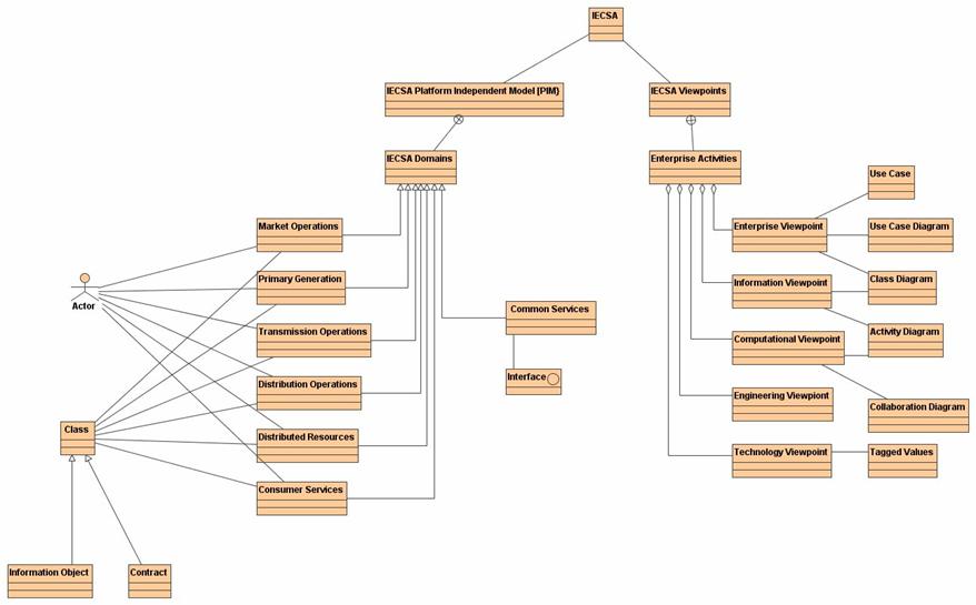
Figure 6: IntelliGrid Architecture Model – Key Concepts
The IntelliGrid Architecture model is organized hierarchy using a set of UML
packages to provide separation of dividing concepts. The IntelliGrid Architecture package at the top level of the
model is the parent for all the concepts modeled in IntelliGrid Architecture. Immediately under IntelliGrid Architecture package is a set
of packages, dividing IntelliGrid Architecture into key concepts.
Each of these key-dividing concepts outlined in this section are
described in detail, in the later sections.
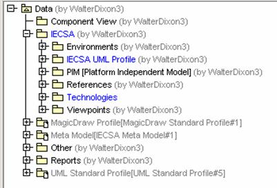
Figure 7:Top level package structure of
IntelliGrid Architecture Model
·
Environments – Contains description of
all IntelliGrid Architecture environments. Different
aspects of IntelliGrid Architecture model will like to the corresponding environment.
·
IntelliGrid Architecture UML Profile – Contains the set of
UML extensions (stereotypes, tagged value definitions, and constraints) defined
by IntelliGrid Architecture in order to convey key RM-ODP concepts as well as the definition
of the key architectural issues the team solicited information on, from
stakeholders during the stakeholder engagement process.
·
PIM [Platform Independent Model] –
Contains the set of information objects, actors that define the system. These objects are technology
independent. The PIM package contains a
child set of packages corresponding the six primary domains specified in IntelliGrid Architecture model.
These domains are represented by UML packages as shown in the
following figure.
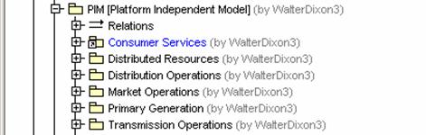
Figure 8: IntelliGrid Architecture Domains
·
Technologies – Contains the set of technologies
and their capabilities.
·
Viewpoints – Contains the set of energy industry
enterprise activities. The viewpoint
package contains a child set of packages corresponding top-level enterprise activities. Each enterprise activity separates the
modeling concepts into 5 child packages, one for each of the 5 RM-ODP
viewpoints as shown in the following figure.
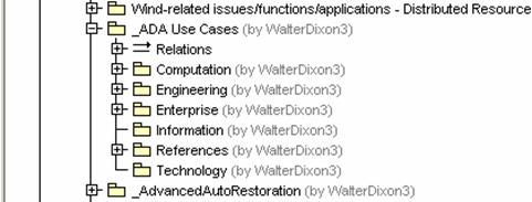
Figure 9: IntelliGrid Architecture Viewpoints Folder
An IntelliGrid Architecture Environment is defined as an environment where
one or more of the information exchanges of Power System Operations functions
have essentially the same architectural requirements, including their
configuration requirements, quality of service requirements, security
requirements, and data management requirements.
The IntelliGrid Architecture Environments reflect the requirements of the information
exchanges, not necessarily the location of the applications or databases
(although these may affect the information exchanges and therefore the
environment).
RM-ODP defines an Environment as the part of the model,
which is not part of that object.[5]. This
essentially represents external complexities in the model, and the
classification of those complexities having similar requirements.
Figure 10: IntelliGrid Architecture Environments
For this RM-ODP concept – the UML collaboration is chosen,
as shown in the figure above, to represent the abstract behavior construct
conveyed by the external influences of the un-modeled elements of the
environment. Additional details for UML Collaborations are shows in the table
below.
|
Collaboration
Additional Modeling Details
|
|
Collaboration Name
|
Corresponds to IntelliGrid Architecture Environment name.
|
|
Collaboration Documentation Attribute
|
Corresponds to the description of IntelliGrid Architecture Environment.
|
|
Collaboration as a Tagged Value Reference
|
The collaboration representing the environment may
appear as a tagged value reference as a means of annotating which steps are
part of which environment.
|
The formal notation of UML includes extension mechanisms
(stereotypes, tagged value definitions, and constraints) that allow UML to
expand its notational constructs beyond those identified in the UML
standard. These extension mechanisms are
critical to the adaptation of RM-ODP concepts.
Tagged values are the primary extension mechanism used by
IntelliGrid Architecture. Tagged values are used to capture
the key architectural issues presented to stakeholders when developing the
domain use cases. These tagged value
definitions are categorized using UML packages as shown in the figure below.
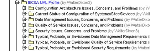
Figure 11: IntelliGrid Architecture Architectural Issues as
Tagged Value Definitions
IntelliGrid Architecture uses stereotypes as a classification mechanism for
the modeling elements defined through stakeholder engagement. A sample of the stereotypes are proved below:
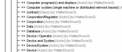
Figure 12: IntelliGrid Architecture Stereotypes
IntelliGrid Architecture uses constraints to capture the invariant conditions
supplied by stakeholders when developing the use cases. These constraints also include pre and post
conditions for describing the various use case scenarios.
Using a technology independent design is an important
concept when developing interoperable systems and equipment today. A technology
independent design must focus on the behavior and structure of the components
within a system and abstract the implementation details of any particular
technology. This key concept allows for different implementations and
technologies to exist, yet still allow these components to be used
interchangeably. Using technology independent design enables a coherent
architecture to be created independently of deployment specifics. When
implemented, the technologies are chosen to meet requirements but are
implemented in a way that complies with the technology independent design.
RM-ODP defines domain as “A set of objects, each of which
is related by a characterizing relationship to a controlling object.”[5] These domains represent the primary division of the
energy industry. It is convenient for
the domain division to correspond to accepted industry practice, as it provides
an immediate partition of the project into smaller areas of interest. However, in order for these systems to be
integrated, there must exist components and services, which cross these domain
boundaries, such as IntelliGrid Architecture Common Services.
·
Market Operations
·
Primary Generations
·
Transmission Operations
·
Distribution Operations
·
Distributed Resources
·
Consumer Services
·
Common Services
RM-ODP and UML each define the concept of Actor. Essentially an actor is any object that plays
a role in the system, meaning any object that can participate in an
action. During the development of IntelliGrid Architecture use cases, a set of actors was developed.
Examples of these actors include:
·
RTOs/ISOs
·
Generation Company
·
Intelligent Equipment Device
|
Actors
Additional Modeling Details
|
|
Actor Name
|
Corresponds to IntelliGrid Architecture Actor Name
|
|
Actor Documentation Attribute
|
Corresponds to the description of IntelliGrid Architecture Actor.
|
|
Actor Stereotype Name
|
The IntelliGrid Architecture actor type appears as a stereotype assigned to
the actor. The stereotype is a means
of classifying the actor.
|
|
Actor Constraints
|
The UML actor constraints correspond to IntelliGrid Architecture
constraints. IntelliGrid Architecture constraint name maps to the UML constraint name. The IntelliGrid Architecture
constraint description maps to the UML constrain expression (non-OCL).
|
|
Actor Operations
|
UML actor operations correspond to the “set” or “get”
methods derived from IntelliGrid Architecture sequence of events.
|
Based on the aggregate set of use cases developed for
IntelliGrid Architecture, the actors developed a set of operations needing to support the detailed
steps of the use cases. These operations
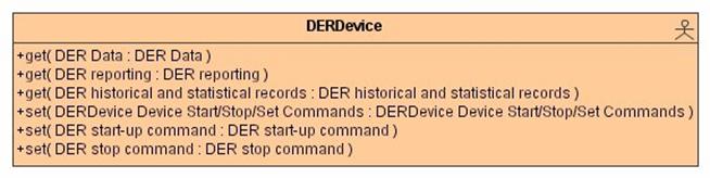
Figure 13: Actor Operations
Each domain except “Common Services” has a set of classes
associated with it. These classes represent IntelliGrid Architecture information objects and/or
IntelliGrid Architecture contracts/regulations.
An IntelliGrid Architecture information object maps to a UML class. An IntelliGrid Architecture
contract / regulation maps to a class having the stereotype
<<contract>>. The IntelliGrid Architecture policy maps to the operations of the
<<contract>> class.
|
Classes
Additional Modeling Details
|
|
Class Name
|
Corresponds to IntelliGrid Architecture information object name or the
contract / regulation name.
|
|
Class Documentation Attribute
|
Corresponds to IntelliGrid Architecture information object description
or the contract / regulation description.
|
|
Class Operations
|
For the <<contract>> class, each policy associated
with the contract is represented by an operation. The name of the operation
is the policy name. The stereotype of the operation is corresponding to the
policy type namely <<>> (for “May” type policy),
<<prohibition>> (for “Shall Not” type policy) and
<<obligation>> (for “Shall” type policy”). The operation
documentation attribute corresponds to the policy description.
|
|
Class Constraints
|
The “Class constraints” correspond to IntelliGrid Architecture
constraints. IntelliGrid Architecture constraint name maps to the UML constraint name. The IntelliGrid Architecture
constraint description maps to the UML constrain expression (non-OCL).
|
Figure 14: Example Class Operations
(Contract)
“Common Services” domain contains a set of interfaces
grouped by common service categories. There are four top-level categories of
common services, namely, “data management”, “security management”, “network and
system management” and “integration and federation”. The top-level
categorizations are represented by UML package.
|
Interface Additional
Modeling Details
|
|
Interface Name
|
UML “Interface name” corresponds to IntelliGrid Architecture interface
name, for example “DistributedDataManagementInterface”.
|
|
Interface Documentation Attribute
|
UML “Interface documentation attribute” corresponds to
IntelliGrid Architecture interface description.
|
|
Interface Operations
|
UML “Interface operations” are IntelliGrid Architecture interface methods.
The IntelliGrid Architecture uses the standard verbs such as:
·
get
·
create
·
change
·
cancel
·
close
·
delete
·
created
·
changed
·
closed
·
canceled
·
show
·
subscribe
·
unsubscribe
|
|
Interface Constraints
|
The “Interface constraints” correspond to IntelliGrid Architecture
constraints. IntelliGrid Architecture constraint name maps to the UML constraint name. The IntelliGrid Architecture
constraint description maps to the UML constrain expression (non-OCL).
|
The IntelliGrid Architecture has the five RM-ODP viewpoints, namely
“enterprise viewpoint”, “information viewpoint”, “computational viewpoint”,
“engineering viewpoint” and “technology viewpoint”. The basic constructs of
these viewpoints are UML use case, use case diagram, class diagram, activity
diagram, and collaboration diagram. Different from IntelliGrid Architecture model, IntelliGrid Architecture
views are organized by enterprise activities and each enterprise activity has
five viewpoints. For example, “Advanced Auto Restoration” is an enterprise
activity.
The enterprise viewpoint is concerned with the purpose,
scope, and policies of the enterprise related to IntelliGrid Architecture. An enterprise
specification of a service is a model of the service and the environment with
which IntelliGrid Architecture interacts. It covers the
role of IntelliGrid Architecture in the business as well as the human user roles and business
policies related to IntelliGrid Architecture. The
Enterprise viewpoint is defined by a set of use cases, collaborations, use
cases diagrams and class diagrams.
The IntelliGrid Architecture enterprise activity is represented by the UML
use case in the MagicDrawÔ. Enterprise activity
contains a set of sub-activities and services, which are also represented by
UML use cases.
|
Use Case
Additional Modeling Details
|
|
Use Case Name
|
A use case will have a name that is corresponding to the
enterprise activity name.
|
|
Use Case Documentation Attribute
|
A use case will have documentation attribute which
contains the description of the enterprise activity.
|
|
Use Case Tagged Value
|
The use case of IntelliGrid Architecture enterprise activity will have
a tagged value that specifies IntelliGrid Architecture function identification number
(function id). The IntelliGrid Architecture function id is a unique identifier of a specific
IntelliGrid Architecture function. The id contains a letter that is assigned to each domain and
a set of numbers delimitated by “.” to show the hierarchy of the functions.
For example, T-1.1 is the id for the “long term load forecast” function in
the transmission operation domain. An enterprise activity could have more
than one function id. For example, the function id for “Advanced Auto-Restoration”
are >>>>. The purpose of capturing the function id is to maintain
the traceability of IntelliGrid Architecture view to the requirements.
|
IntelliGrid Architecture includes two concepts in use case diagrams. To convey organization and hierarchy, a use
case diagram will show the relationship between a high-level use case, and
lower level use cases. For example:

Figure 15: Use Case Hierarchy
As shown in the Figure
15: Use Case Hierarchy the Advance Auto-Restoration use case – includes a
number of subordinate use cases. The
subordinate use cases are linked through an “<<include>>”
dependency.
The second concept modeled in IntelliGrid Architecture use cases is that of
actor involvement.

Figure 16: Example Use Case
The Figure
16: Example Use Case diagram shows the set of actors directly involved in
the Advanced Auto-Restoration use case.
RM-ODP defines Community as “a configuration of objects
formed to meet an objective. The objective is expressed as a contract that
specifies how the objective can be met.” [5]. This concept
maps well to the UML Collaboration, which is defined as an abstract structuring
concept. The members of the
collaboration represent cooperative elements that come together to meet a
specific objective.

Figure 17: Example Community
Membership in the community is defined by the set of UML Role
Classifiers owned by the community. The
role Classifier has a base classifier set to the corresponding actor.

Figure 18: Example Community Membership
|
Collaboration
- Additional Modeling Details
|
|
Collaboration Name
|
Corresponds to IntelliGrid Architecture Grouping (Community) name.
|
|
Collaboration Documentation Attribute
|
Corresponds to IntelliGrid Architecture Grouping (Community)
description.
|
|
Owned Elements
|
Membership defined through the set of owned Classifier
Roles.
|
The class diagram is used to expose the contractual
bindings of the actors. A UML class represents IntelliGrid Architecture contract/regulation
and IntelliGrid Architecture policies are represented by the operations in the class.

Figure 19: Contract Governing Actors
As shown in the figure, the two actors are associated with
each other with a contract called “Competition between neighboring utilities”
binding the interface. The binding is shown by the UML “permission”
association.
The information viewpoint is concerned with the semantics
of information and information processing.
The information specification of IntelliGrid Architecture is a model of the information
objects that the system holds and the governing states of the system. The information viewpoint is defined by a set
of information objects (classes), activity diagrams conveying system state and
class denoting static structuring concepts.
The activity diagram is used to describe IntelliGrid Architecture
enterprise activity sequence of event together with the collaboration diagram.
The IntelliGrid Architecture sequence number maps to the UML transition name attribute. The IntelliGrid Architecture
event maps to the guard condition expression o the transition. The name of the
process / activity maps to the UML “action state”. The “description of process
/ activity” maps to the action state documentation attribute. The “name of info exchange” maps to the
“Object Flow State”.

Figure 20: Activity Diagram (part-of)
The computational viewpoint is concerned with the
interaction patterns between the components (services) of IntelliGrid Architecture, described
through their interfaces. A
computational specification of a service is a model of the service interfaces
seen from a client, and the potential set of other services required by that
service. The computational model defines
types of interfaces such as request/reply or publish/subscribe or whether an
interface is designed for exchange of real time or historical data. For example,
interfaces may be defined as API’s such as CCAPI’s Generic Interface Definition
or as a wire protocol such as UCAÒ’s
device oriented services.
Computational Viewpoint is represented by UML collaboration and activity
diagrams.
The collaboration diagram is used to describe IntelliGrid Architecture
enterprise activity sequence of events. The role classifier of the
collaboration diagram corresponds to IntelliGrid Architecture “information producer” and
“information receiver” with the existing actors as their base classes.

Figure 21: Collaboration Diagram
(part-of)
1.1.1.1.1
Message
The message “Action type” is set to be “call” action
having the name of IntelliGrid Architecture “name of process/activity”. The “call” action
documentation attribute corresponds to IntelliGrid Architecture “description of process/activity”.
The engineering viewpoint is concerned with the design of
heterogeneous aspects, of the information infrastructure required to support
distributed systems. The engineering
viewpoint is the least defined viewpoint of IntelliGrid Architecture, since this viewpoint is
closer to the implementation details than current project scope permitted to
define. The current IntelliGrid Architecture engineering
viewpoint includes a set of diagrams collected during the stakeholder
engagements. Future work, perhaps
confined to specific projects using IntelliGrid Architecture, shall develop this viewpoint.
The technology viewpoint is concerned with the provision
of an underlying technology infrastructure, consisting of a set of technology
related capabilities and recommendations. The technology viewpoint, like the engineering
viewpoint, is closer to the implementation details than current project scope
permitted to define, however, significant technology related details are
presented through a set of class definitions.
These classes are annotated with a set of UML tagged values, expressing
the technology capabilities.
This page intentionally left blank.
|
