|
In accordance with the utility industry
specifics, and the standard bodies common architecture development process, the
team put together an RM-ODP-based architecture development methodology along
with the appropriate template to collect requirements based on RM-ODP
components. The team’s architecture development process is shown in Figure 2: Architecture Development Process.
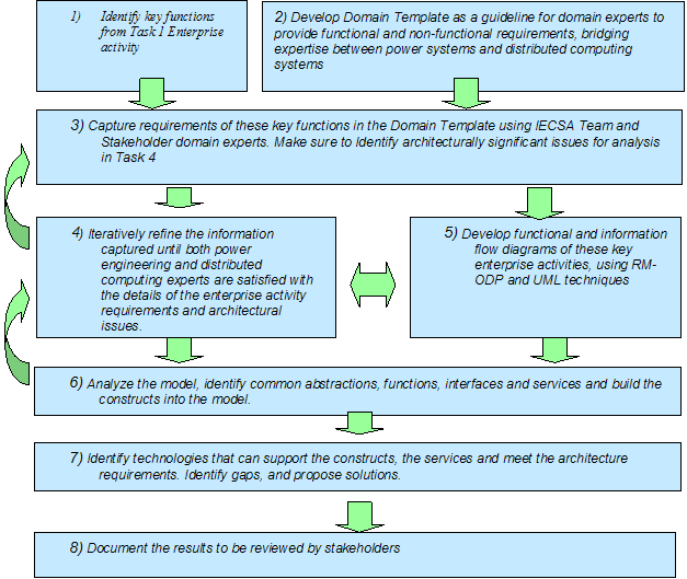
Figure 2: Architecture Development Process
In step 1, the team identified a set of power
system functions and operations, which expose architecturally significant
requirements. This step was discussed in details in Volume II. Completion of
this step provided the team with a starting set of functions to investigate and
use to capture the requirements. Amongst other considerations, the significant
criteria used in selection of Functions are listed below.
Functions that span across multiple power
systems business domains – Cross-domain Use Cases expose the need for
common, horizontal services in the architecture. For example, Real Time Pricing
(RTP) applications span across Energy Service Provider, Market Operations,
Distributed Resources, and Consumers domains. Significant inter-domain
interactions and coordination amongst the entities are needed to assure proper
operations. This is a collaborative problem solving application that requires
involvement of different organizations and thus exposes the need for
appropriate architectural support. Examples of requirements include assuring
end-end network management capabilities to meet Quality of Service (QoS) and
reliability requirements, development and enforcement of cross-organizational
security policies to meet security requirements, and finally inter-domain
coordination of activities to access timely data.
Functions that are critical to the
operations of the self-healing grid – Such Use Cases expose the
requirements and the resulting architectural needed to support the self-healing
grid. For example, inclusion of Advanced Distribution Automation (ADA) and Wide
Area Measurement and Control (WAMAC) provide to the architecture the
requirements of self-healing functions. They emphasize the need for real-time
response, proactive measurement and test, secure operations environment and
availability of uncorrupted critical data for decision-making.
Functions that expose the requirements for
new and emerging services - These Use Cases provide the architecture with
what future and emerging services are expected to look like and the type of
support needed for the underlying communications architecture. Examples of new
and emerging services are shown in the RTP case, in areas such as home
automation, trading services and advanced load balancing. Also, Use Cases such as ADA and WAMAC expose
the requirements of the real-time sensitive, and computationally intensive
components.
In parallel with Step 1, in Step 2, the team
developed a domain template to collect the functional and non-functional
requirements with emphasis on architecturally significant requirements of the
Use Cases. The template is heavily based on RM-ODP concepts and views. Yet, the
template was strategically designed to be devoid of technical jargon so that
the domain expert could express concepts in natural language and his/her own
nomenclature. The template has been discussed in more details in Volume II
Appendix C. The importance of the domain template was its ability to provide a
uniform framework for capturing the requirements, and its ability to simplify
the move from requirements capture to analysis through use of RM-ODP-like
concepts.
Finally, in Step 3 the requirements for the
Use Cases were captured through frequent interactions with stakeholders and
other domain experts, as well as use of existing documents and research
results. The IntelliGrid Architecture team, in order to capture the detailed functional and
non-functional system requirements, consulted multiple information
sources. Figure 3 illustrates the various sources and the way the
requirements were transferred into the UML model. In most cases, the information was input into
the UML model by a JavaÔ program interfacing
with MagicDrawÔ
API. The program reads the well-structured completed domain template, builds
the UML constructs and diagrams, and populates the UML specifications. More
details on this program is given in Volume III Appendix A
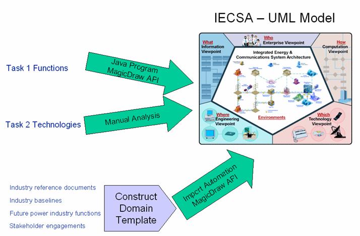
Figure 3:
Migration of Requirements to the Model
The sources of information/requirements
include:
·
Task
1 Functions – The team used information on approximately 400 present and future
utility functions that were identified during Phase 1 of IntelliGrid Architecture project.
These functions collectively expose the requirements for IntelliGrid Architecture. These requirements
were input into IntelliGrid Architecture UML model automatically from the Excel sheet, using a
JavaÔ program in conjunction with the
MagicDrawÔ API. For a complete list of these
functions, see Volume II Appendix F.
·
Task
2 Technologies – The results of the Task2 Existing Technologies &
Standards investigation are incorporated into the models manually where
appropriate. These technologies are included where the specific functional and
non-functional requirements need to be met. Some of the technologies are
further described and specific recommendations are made in Volume IV, Section
3.
·
Industry
reference documents – The industry reference documents were used to enhance and
complement the requirements captured in the domain templates. As a result of
automatic porting of the requirements, the industry reference information was
also included into the model. IEC TC57 documents are examples of such
documents. Additional documents are listed in Volume II Appendix A.
·
Industry
baselines – Requirements for industry baseline functions were captured through
the domain template and input into the model automatically thorough the JavaÔ API to MagicDrawÔ. An example of a baseline function is Emergency
Operations Baseline, part of the Wide
Area Measurement and Control Use
Case.
·
Future
power industry functions – This information was obtained by IntelliGrid Architecture team’s
research and stakeholder involvement. Again, the information is included into
the model through construction of a domain template for each such functions and
automatic porting of the templates into the model. ADA in its entire form is an example of a
future power system function.
·
Stakeholder
engagements – The IntelliGrid Architecture team hosted numerous meetings with stakeholders that
resulted in the elaboration of the contents of the filled domain templates and
incorporation of significant requirements. The stakeholder engagement strategy
is outlined in Volume II Appendix A and the list of stakeholders engaged can be
found in Volume II Appendix B.
In Step 4, the information in the filled
templates and the model were analyzed, through multiple iterations and
communications with the stakeholders and other experts. The UML model that was
initially populated by the automated routine was refined to include more specific
information and constructs. As a result of the analysis, the filled templates
and the UML model were modified to assure consistency and accuracy within the
model and across to the other requirements. Figure
4 illustrates that the analysis process involves the
nexus between textual tools (MSWord and Excel) and UML tools. The analysis is
shown as a black box in the figure to suggest only that a rational process is
required and that the results (rendered architecture) flow from the inputs (Raw
sources & Domain Templates). There was no predisposition as to where and
how the analysis was conducted. However, the process chosen is described
herein.
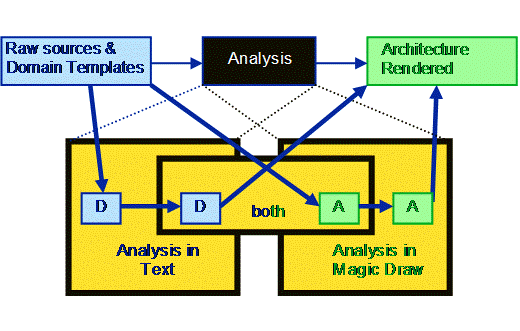
Figure 4: Analysis of Filled Domain Templates and the UML Model
The analysis and refinement resulted in
creation of normalized source material so that common actors, data elements,
functions and interfaces that are the same but have slightly different names
can be adjusted to a single representation wherever it is used. The tools of
analysis preserved the relationship between normalized components and the
original sources.
As a result of some preliminary analysis, the
team decided to define the notion of environment for the purpose of
giving a subset of requirements a context, or environment, within which they
need to be satisfied. This was essential for the development of solutions since
solutions depend on the environments within which they need to be applied. For
example, a requirement of 5-second response time may have a different solution
whether the requirement is for a function within a substation environment with
a tightly managed Intranet or within a consumer eCommerce environment with
public Internet as the means of communication. More details on environment can
be found in Volume IV Appendix E.
The normalization process was accomplished
via the following steps:
1)
Import
Domain Template into UML tool using custom import tool
2)
Observe
anomalies in imported model due to inconsistencies in naming usage.
3)
Correct
Domain Template in text editor, with help and input from the stakeholders as
necessary, and repeat step 2 until anomalies are resolved
4)
Import
all domain templates into model
5)
Use
custom report generator tool to produce a summary of all nomenclature used for
actors, information items, etc.
6)
Find
terms used in different domain templates that represent the same items except
from the perspective of a different author
7)
Resolve
the naming overlaps and conflicts in individual domain templates
8)
Import
again for final time – resulting in normalized domain templates and model
elements
The following table summarizes Domain
Template quality attributes to be ensured prior to completion:
Table 2
Domain Template Quality Checks
|
Make sure that the narrative is self
contained and that everything mentioned in the narrative appears in the
remaining sections. Ensure that the nomenclature used in the remaining
sections matches that used in the narrative.
|
|
If this document is related to other
documents done by the author or others, the narrative should begin with a
summary of this relationship. Introductory material that is taken from the
other documents to allow this document to have a context should be clearly
identified as such so that its description is not expected in the rest of the
template.
|
|
Make sure the names of the actors as listed
in Section 1.5 are consistently used throughout the document (specifically in
Sections 1.8 and 2.1 of the template). Note that the automated routine is not
a spell checker, nor is it a reasoning engine to discover what the author
really meant. Check also for common capitalization, small differences in
usage, abbreviations vs. whole words (i.e. ESP and elsewhere Energy Service
Provider). Note: You may denote a list
of actors using comma as a separating character. This is important since the use of
different terms for the same entity – will result in the creation of two
separate modeling elements – where only one should exist.
|
|
In Section 1.8 of the use case, the
policies belonging to a contract should immediately follow that contract in a
table. Thus, for any contract in the contract table, there could be a set of
zero or more policies that follow it immediately. Check with the domain expert
to make sure that all the contract/policy pairing is observed. A common
mistake is to put all contracts first in a table, follow by all policies in
the next table. In such a case, the policies will all be placed part of the
last contract on the contract table.
|
|
Delete empty rows and empty tables.
|
|
In the sequence tables of Section 2.1. Make
sure that there are primary, information producer and information receiver
actors and further they are all valid actors of 1.5.
|
|
In the sequence tables of Section 2.1. The
primary actor is either an information producer, or receiver. By definition a
primary actor is one that initiates the activity.
|
|
Make sure there is a “Domain Template
Architectural Issues” spreadsheet in Section 2.2. is correctly filled in.
Ensure that the steps in the columns are the same as the row identifiers in
the word section. Also, these labels must be in row 4 of the spreadsheet.
|
|
For each diagram – fix diagram layout.
Ensure that the terminology in the diagram match up with the terminology in
the narrative and body of the filled in template.
|
Step 5 includes the task of modifying the UML
model and rendering the results of the analysis in parallel with step 4.
Throughout the analysis phase, the automatically generated diagrams and model
elements were modified to reflect the normalized, and refined model components
that express the RM-ODP viewpoints. The UML model can be navigated use a web
browser – see Volume III – Appendix A.
In Step 6, the team massaged and further
analyzed the resulting model to separate common elements and interfaces that
isolate domain specific functions from horizontal services that are elements of
the emerging “architecture” and would support the domain functions. The team
further investigated into the requirements and refined the model to extract and
add the common services that satisfy the requirements in whole or in part, to
align well with industry defined common services and abstractions. Example of a
common interface is one where data is provided accurately and timely on a
specific platform to be accessed by the application. Examples of a common
service is the service to provide a transport of a specified BW, or one that
provides reliable communications through performance monitoring and timely
alarm processing. As these services were identified, they were incorporated
into the model. The common interfaces and services are further elaborated and
listed in Volume IV – Appendix D.
Following analysis and identification of the
common interfaces and services, the team investigated the various
technologies/best practices/standard activities that provide solutions for the
constructs and meet the requirements of the architecture, the interface,
services and functions. The team followed a non-judgmental initial approach by
considering all mature, new, or emerging technologies, as well as the
activities of the standard bodies and the best of common practices. The team’s
starting point on technologies was the list of Existing technology and
Standards of Task 2. This list was further filtered and reduced in size
according to the following considerations:
·
The technology is mature and universally used.
Thus, any further discussions and recommendations of it will be trivial.
Examples include SONET/SDH, IS-IS/OSPF routing, or ITU modem technologies.
·
The technology is not closely related to the
architecture and its emphasis. For example, IEEE MAC addresses.
·
The technology is not applicable to any aspects
of the functions or the requirements. For example, Voice over IP, and all other
voice communications technologies.
A subsequent analysis of the remaining
technologies identified to the resulting model – what is the match between a
specific technology and the abstracted requirements of IntelliGrid Architecture. The team made
sure that the solution satisfies the functional and non-functional requirements
and determined the feasibility of the architecture given the constraints of
existing technologies. Through this analysis, the team identified other
technologies that were not in the list. Throughout this process, the team was
more inclusive than exclusive. We included all applicable technologies and
provided the tradeoffs where appropriate. Furthermore, the team suggested
modifications/new approaches to the use of these technologies for the purpose
of meeting the specific requirements. An example is the proposal on putting
together a unified Enterprise Management system (see Volume. IV, Section 1.3).
The IntelliGrid Architecture technology viewpoint is constructed
during this stage. This viewpoint is built upon the existing and emerging
technologies and standards, such as Utility Communications Architecture (UCAÒ), IEC TC 57 series of standards (IEC
61850, IEC 61970), and others – including those not specific to the Power
Industry. In this process, the team also
identified technology gaps. The technologies and analysis of technology gaps is
described in Volume IV.
The results of IntelliGrid Architecture analysis work are
documented in Volume IV. Intermediate
results have been made available as part of the document review process. Review comments were addressed and
incorporated into the IntelliGrid Architecture framework.
|
