|
The communication
infrastructure of IntelliGrid Architecture should support restoration technique(s) that offer a
wide-range of services that meet varying resiliency requirements of
applications. From the end-user standpoint, the restoration attributes of most
interest are restoration time, the failure coverage, and network capacity
needed for protection and restoration. Restoration time is the time taken to
restore the end-user service upon failure. This includes in general, failure
detection, notification and switch-over of the traffic
to an alternate path.
In this appendix, we review
a number of state-of-the-art and emerging solutions for survivable services
supported by various networking technologies.
We first discuss application-based solutions that assume minimum or no
support for recovery operations from the network. A brief summary of some familiar
network-based solutions and protocol supports is then presented. The rest of this section focuses on
discussing several emerging techniques and protocols including the problems
they intend to address and key solution characteristics. These selected techniques
and protocols are discussed in order from higher to lower protocol layers. It is interesting to note that significant
tradeoffs exist in terms of their scope, complexity/cost
and flexibility as services are provided to the protocol layers above. At the
end, we provide a list of references used in for the material in the appendix.
Application-based Solutions
Application layer resilient solutions can be categorized
based on the level of transparency with respect to the application client. In one extreme of the spectrum, redundancy and
fault tolerance of the application server is supported in a manner that is
entirely invisible to the application client(s). Examples of such type include
cluster-based database/ transaction servers with hot standby as well as
fault-tolerant controllers for telephony switches and/or routers. In this type of solutions, when the primary
server/controller fails, the backup one takes over its responsibility
automatically with minimal service hit towards the application client. In some
cases, the application client may not even notice the switch-over of service
between the primary and backup server/controller. Such high-level of transparency comes at a
high implementation cost, as it requires tight synchronization of application
states between the primary and backup servers.
Additional "watchdog" device is often required to closely
monitor the health of the primary server and activate the backup server when
the primary one fails. Alternatively, the primary and backup servers can
periodically exchange "heart-beat" control messages with each other
to detect any failure of its counterpart.
In the other extreme of the application client-transparency
spectrum, the application server redundancy is completely exposed to the
application client. In fact, it is up to
the application client (or even the application end-users) to select the server
of choice, e.g. based on geographical proximity or observed unavailability of
the servers. Mirroring FTP servers as well as redundant DNS name servers are
good examples of such type of solutions. By shifting the burden of server
selection and/or fail-over decision to the application client, tight
requirements on application-state synchronization and heart-beat monitoring
amongst the servers can be relaxed at the expense of longer detection and
recovery time (i.e. switch-over to a different server) upon server
failure. However, the cost of hardware
and storage redundancy to support multiple servers remains.
In addition to the extreme types of application server
resiliency described above, there is a continuum of solutions that vary in the
degree of synchronization or coupling among the servers as well as the
distribution of the fault detection and recovery responsibilities. Such
responsibilities can be distributed across the application server, client and possibly some intermediate servers. For example, in the case of a
load-balanced/fault-tolerant web-server farm [7,8,9],
the existence of multiple web-servers in the farm is not visible to the
application client, i.e. the web-browser. Neither are the web-servers in the
farm aware of the presence of each other.
Instead, an intermediate server or dispatcher monitors the availability/
loading of the web-servers and directs an incoming client request to one of the
web-servers. Such direction can be accomplished by (1) having the dispatcher to
overwrite the destination address (IP or MAC address) of the incoming packets
to that of the selected web-server, or (2) letting the dispatcher to act as an
authoritative DNS server which maps an incoming URL request to the IP address
of the selected web-server within the farm.
Application-layer resilient solutions are unique in their
ability to protect against communication end-point (the server-side) failures.
There is a wide spectrum of application-layer resilient solutions, which
enables the trade-offs between implementation complexity of various
communication endpoints and the responsiveness of fault detection and
recovery. In general, their deployments
are usually based on not only fault-tolerance considerations but also, if not
more importantly, scalability and load balancing concerns.
Limited Resilient Services Supported by Generic TCP/IP Services
As one of the most popular and dominant data networking
protocol suite, TCP (Transmission Control Protocol) was designed to provide
reliable stream data delivery service for those data applications that demand
it. A number of mechanisms including
ACK, time-out, retransmission, sliding windows plus the congestion control have
been developed over time to improve the robustness and performance of the
service in the presence of various disruptions and to accommodate different
characteristics of the underlying network.
Further, a well-defined set of procedures governs the closing and reset
of a TCP connection under various conditions.
All these services are provided on top of an unreliable
connectionless packet delivery service provided by the IP network layer
protocols. Key elements in supporting the resiliency at the IP network layer
include failure detection mechanisms through e.g., (the lack of) hello messages
exchanged between neighboring nodes and the notification mechanism such as the
flooding of LSAs (Link State Advertisement
Packets). For hop-by-hop routed IP
networks, the recovery is automatic and best effort in nature as the routing
tables get updated in a distributed and asynchronous manner. Each packet hopefully will be delivered to
the destination IP address eventually.
FR/ATM (Frame Relay/ Asynchronous Transfer Mode)-based Solutions
As mature protocols, substantial amount of efforts in
standardization of Frame Relay and ATM has taken place. Taking ATM as an
example, ITU-T recommendation I.630 defines the architectures and mechanisms
for protection switching at ATM layer including the use of OAM cells and a
control protocol using special APS cell [13].
With the initial assumption of the SONET/SDH transport layer
underneath and the strong interest by the network operators, it is not
surprising that 1+1 and 1:1 protection switching are the main mechanisms
whereby protection resources are pre-allocated for individual or a group of
working VP/VC (Virtual Path/Circuit).
The protection domain may span across a network connection, or a sub-network,
or a single link connection.
In the 1+1 protection architecture, there is a dedicated
protection entity for each working entity. The traffic is sent simultaneously
to the receiver or sink of the protection domain on both working and protection
entities. Selection between the working and protection entity is made based on
some predetermined criteria, such as defect indication.
In the 1:1 protection architecture, the dedicated protection
entities, in contrast to the 1+1 case, only carry the traffic it is protecting
when the working entity has failed or was forced to switch by command. Thus the
dedicated protection entities may be used to carry extra traffic during normal
operations.
Yet another resiliency technique in FR/ATM is to use Soft
PVC/PVP (Permanent VC/VP) [14]. In this
approach, the edge switch utilizes the SVC/SVP (Switched VC/VP) signaling and routing
protocol supported in the network to route around the failure in the network
such that the PVC/PVP service provided and terminated at the users would not be
disrupted.
Ethernet-based Solutions
Ethernet is undoubtedly the most widely deployed OSI layer 2
(L2) network technology. One of the keys
for its success is the low capital, management and operation costs. In
particular, the IEEE 802.1D standard [15] defines the distributed spanning tree
protocol (STP) to support the self-configuration of loop-free Layer 2 (L2) packet forwarding topology over a set of
physical local area network (LAN) segments interconnected by bridges. The STP provides a resilient function in the
sense that, upon physical topological changes, e.g., due to link
/node/bridge-port failures or addition of new bridges/LAN segments, the STP
will coordinate the reconfiguration of the participating bridges to maintain a
loop-free L2 connectivity. During such reconfiguration, the STP algorithm
selects a set of bridge ports and brings them to a blocking state so that those
ports (a.k.a. the alternate ports) no
longer forward L2 user frames. By restricting the L2 forwarding topology to a
tree, loop-free L2 forwarding is achieved.
With the "spanning" nature of the tree, L2 connectivity is
provided among any pair of L2 endpoints within the network, physical topology
permitting.
One of the problems of using STP for L2 bridged network
reconfiguration is its poor convergence time, attributable to two factors.
First, the failure detection of STP relies solely on a passive age-out
mechanism with a recommended default value of 20 seconds for the so-called Max-age parameter, assuming a delay
variance of 2 seconds per bridge hop and a maximum of 10 hops within a bridged
network.
Second, once a network failure is detected and a new
spanning tree is recomputed, it takes even longer before the new tree can
resume data forwarding. This is due to
the extremely conservative approach taken by the STP to prevent the formation
of transient L2 forwarding loop during topological changes. To eliminate the
formation of transient L2 loop caused by inconsistent views held by different
bridges within the network, the STP does not allow a previously blocking port
become a forwarding one until the information/events which trigger such
transition are received/observed, and acted on by all
other bridges in the network. As such, the protocol imposes a minimum
transition latency of twice the maximum forwarding delay within the network (as
defined by the Forward-Delay parameter). The default value of 15 seconds for
the Forward-Delay parameter, together with the 20-second Max-age timeout,
brings the minimum recovery time of the STP to ten's of seconds.
SONET/SDH-based Solutions
SONET/SDH is by far the most common optical transport
technology. It was developed to provide reliable and fully manageable high
bandwidth transport [26,27]. SONET/SDH technology
includes various automatic protection switching (APS) schemes that are provided
for fast automatic recovery from failures at the optical layer. The two most
common of these APS schemes are based on SONET self-healing ring architectures:
Unidirectional Path Switched Ring (UPSR) and Bi-directional Line Switched Ring
(BLSR). They are widely deployed in the
infrastructure networks and provide extremely high reliability and fast
recovery (sub-50ms under some assumptions [28]) to most services offered today,
ranging from telephony, private line to packet data services such as IP and
FR/ATM.
In general, UPSR is the simplest ring architecture. For
protection switching, it does not require any coordination between the exit and
the entry nodes. However, compared to other ring architectures such as BLSR,
which is discussed below, it may use more bandwidth for the same traffic. The
bandwidth requirement of UPSR is the maximum bandwidth required over any span
or between any two adjacent nodes on the ring. It uses its capacity most
effectively when the traffic on the ring is between a hub node and all other
nodes. Therefore, UPSR provides a simple and low cost solution for access
networks where traffic is being hub from all other nodes to a common gateway.
Unlike UPSR, BLSR architecture allows sharing of the protection
capacity among different failures on the ring. Therefore compared to UPSR, BLSR
has better capacity utilization. Also, under no failure condition protection
capacity can be used to carry extra traffic. This provides opportunity to
service providers to generate additional revenues. However, all this comes at
the cost of more complexity in signaling as, unlike UPSR, coordination between
nodes is required.
Besides the Ring-based APS scheme, SONET/SDH also supports
point-to-point 1:N as well as 1+1 APS architectures.
In a 1:N scheme, N working fiber systems share one
protection fiber system where the working and protection fiber systems are
placed in the same physical route.
Signals are transmitted on working lines during normal operations. When
fault is detected in any one of the N working systems, the receiver and
transmitter exchange alarm control messages which cause the failed system to
switch to the protection system.
Like the UPSR scheme, a 1+1 scheme, the system transmits the
signal continuously on 2 diversely routed working and protection fiber systems.
The receiving terminal monitors received signal quality on both working and
protection systems and selects signals from the protection line if the received
signals from the working line do not meet performance requirements. Since the
receiver continuously receive signals from both the working and protection
system, UPSR as well as 1+1 APS can provide the fastest restoration time by
avoiding any traffic re-route/switch delay upon failure, but at the expense of
doubling the bandwidth/traffic to be sent across the system.
SCTP (Stream Control Transport Protocol)
As discussed above, resilient feature of transport layer
protocols (a.k.a. Session layer or Layer 4 in OSI/ISO terminology), e.g. TP4 or
TCP, has largely been limited to the support of retransmission of the transport
protocol data units (TPDU) upon data loss or corruption. For most existing
transport layer protocols, a L4 session is typically bound to a single network
interface (and thus a single Layer 3 address) at each end-host which
terminates/participates in the communication session. Such one-to-one correspondence between a L4
session endpoint and an end-host L3 address has tied the fate of a L4 session
to that of the end-host network interfaces it traverses. Under such setup, session layer resiliency
has become synonymous to network layer resiliency between the end-host
interfaces. In an effort to enhance
session-layer resiliency and transport performance, research proposals [32,33,34] that advocate the decoupling of session-layer
endpoints from their hosting interfaces have surfaced for quite some time. In
particular, such proposals allow the use of alternate interfaces and the
splitting of TPDUs over parallel network paths to reach
the destination L4 end-point.
Recently the Stream Control Transport Protocol (SCTP) [35] has been published as an IETF RFC. Under the name of "multi-homing support for
SCTP", the decoupling/ splitting approach is, for the first time,
incorporated in a real-world transport protocol. The design of SCTP is strongly
motivated by the use of unreliable IP networks to transport mission-critical
signaling/control messages similar to those found in traditional public telephony signaling
architecture [36]. SCTP provides a full-duplex, connection-oriented Layer 4
point-to-point session, which guarantees reliable, ordered delivery of messages
using selective acknowledgement (SACK) and timeout/ retransmission mechanisms
similar to those of TCP. It also
supports congestion and flow control using TCP-like window-based mechanisms.
A session is referred to as an association in SCTP terminology. Each endpoint of an association
can be bound to one or more end-host interfaces, each having a different IP
address. Once a multi-home association is setup, the TPDU's (as well as other in-band control messages)
can be transferred over separate network paths by using different combinations
of source/destination IP addresses of the corresponding end-host interfaces. Figure 1 depicts a multi-homed SCTP association where a1 and b1 are the primary IP addresses of Host A and B respectively.
Figure
2 shows the state transition diagram governing the 3-phase
fail-over process between the primary and alternate path of the SCTP
association. Under the "Normal" phase, new TPDUs
are transmitted to the primary address of the destined association end-point,
i.e. from a1 to b1, unless the SCTP user explicitly specifies the destination (and
possibly) the source IP address to use. Upon a retransmission timeout (RTO)
(due to primary path loss/error), the association enters the "Watch-out”
phase in which the source attempts to select the most divergent source-destination
pair, i.e. a2-b2, from the original
primary path to perform the retransmission. New incoming data are still sent
along the primary path during the "Watch-out" phase. In the meantime, the source endpoint will
closely monitor the status of the primary path by (1) sending periodic
heart-beat messages (with exponential back-off) to the primary destination
address a1 while keeping track of the
number of RTOs and that of missing heart-beat acknowledgements. If the sum of these two counts exceeds a
so-called Path.Max.Retrans threshold, the primary
path will be declared to be inactive and the association enters the 3rd
"Fail-over" which continues until the positive acknowledgements of
data or heart-beat messages is received from the original primary destination
address.
Figure 1 A Multi-Homed SCTP Association
Figure 2 State Transition Diagram of the SCTP
3-phase Fail-over Process
While SCTP has already become a proposed IETF standard since
October 2000, practical deployment of the protocol is still in its infancy. In
fact, recent research has discovered various potential performance problems
[44-48] with the current fail-over mechanisms of SCTP. In particular, it has
been found that the current 3-phase fail-over approach tends to be overly
conservative in sticking with a poorly performing primary path. There is also
an unfairness problem against other TCP sessions due to SCTP congestion window
size overshoot during the fail-over between different parallel network paths.
Related performance studies of the SCTP can be found in [49,50]. We conclude our discussions on SCTP by
emphasizing that, a multi-homed SCTP session by itself does not guarantee
resiliency. It merely provides the interface points and control mechanism to
select between parallel network paths. It is the responsibility of end-users
(with help from the network service provider) to provide network path diversity
in order to achieve true transport-layer resilience.
Emerging IP/MPLS-based Solutions
Multi-Protocol Label Switching (MPLS) is poised to be the
convergence technology that combines advantages of the dominant L3 IP routing
protocols and connection-oriented L2 techniques including fast forwarding and
traffic engineering. It has thus become
possible to use MPLS to support more stringent resiliency requirements that
could not be supported by hop-by-hop routed IP networks. IETF has published a framework for
recovery in MPLS based networks [52].
Several solutions and techniques have also been proposed and discussed
in the standards forum and literature.
They include:
LSP 1+1: This is
conceptually similar to the well-known SONET/SDH linear 1+1 and ATM APS 1+1
discussed earlier in which two diverse paths are setup between two peering entities. One Label Switched Path (LSP) is designated
working while the other as the protection LSP.
Detection of the failure at the receiving entity of the working LSP
would trigger the switchover from the working to the protection LSP. Since data are continuously sent over both LSPs from the sending node, the switchover time and the
service hit can be kept at a minimum.
Clearly associated management and signaling functions are required for a
complete solution. ITU-T SG-13 draft
recommendation Y.1720 [53] discusses in great length this architecture.
Packet 1+1: In
contrast to the LSP 1+1, a novel 1+1 solution has been proposed which is at the
packet level [54,55].
In this solution, both LSPs are considered
working and again, data are duplicated and transmitted by the sender to the
receiver. The receiver in this case,
using a clever but simple algorithm, forwards the first received copy (thus no
buffer required) and drops the duplicate copy which may arrive later. As a result, a hitless and instantaneous recovery is
achieved.
Fast Local ReRoute (FRR): Both
solutions above are path-based in the sense that only sender and receiver of
the connection are service aware for the recovery. Another approach is to perform repair and
recovery locally when a link or node failure is detected. Such an approach in principle can make the
recovery faster if the delay is dominated by the communication and number of
nodes traversed between the nodes. One solution that has been discussed
actively in IETF is the "Fast ReRoute"
[56]. The basic idea is to have the
neighboring node create and use detours to route around the failed entities
such as a link or a node.
Shared Packet Mesh:
One implication of the local repair solutions such as FRR is the likely larger
amount of additional capacity required to assure reroute would be
successful. Thus FRR suggests that the
solution is intended for temporary repair and assumes peripheral and other
actions will be supported for longer time scale concerns such as capacity
efficiency. A new path-based solution
has been proposed and discussed recently [54] that addresses the balance of
restoration time and capacity efficiency.
In essence, the shared packet mesh solution allows for the sharing, as
opposed to dedication, of the network protection capacity for all working LSPs against (typically single) failure, thus achieving a
much higher degree of capacity efficiency.
Note that the well-known 1:1 and 1:n protection
concepts can be considered as special cases of the shared mesh.
Some quantitative studies have indicated that a saving of
over 30-40% of capacity is possible in typical networks compared to the 1+1
solutions. There are of course
additional protocol supports required for such a solution especially for
distributed implementation at each node of the network. Some degree of sharing and thus saving of
capacity can be achieved with extensions to signaling protocols such as RSVP-TE
[57]. However to support a network
optimization, extensions to routing protocols such as OSPF-TE [58] and a new
class of algorithms are needed [59].
Discussions of this architecture and solution in ITU-T SG-13 are
ongoing.
Rapid IP route recomputation:
Through configuration and tunings, this scheme can provide restoration as fast
as in the order of several seconds. Compared to the fast-local reroute scheme,
this larger restoration time allows efficient utilization of restoration
capacity. This scheme also provides better failure coverage than the fast
local-reroute scheme as it protects against all Layer-1, and certain Layer-2
and control plane failures. In particular, it uses a smaller OSPF hello timer
to speed up the detection of failure and immediately notify the rest of the
network of the topology change due to through OSPF flooding. This will stretch failure detection and
notification of this scheme over a period of around 1 sec. From the topology
change information, each node figures out the exact failure in the network as
well as the primary paths affected by it. Using RSVP, then it immediately
initiates setup of protection LSPs for all the
affected LSPs for which it is the source node. Once
the path is established the traffic starts flowing on the new LSP. Note no
explicit switching is required. By using path-based protection, this scheme provides
recovery from any single link or node failure in the network.
Slow restoration based on RSVP-TE failure recovery:
In this scheme, no effort is put to improve the failure recovery time. In case
of a failure, periodic PATH message used for refreshing the soft state of an
affected LSP establishes LSP along a different path, taking a detour around the
failed link or node. Once the path is established the traffic starts flowing on
the new LSP. Note no explicit switching is required. In addition to the layer-1
failures this scheme also covers some control plane failures. Restoration time
of this scheme is many 10s of seconds.
Many different types of failures are possible in a MPLS
network such as physical layer (e.g., fiber cut), link layer failures, signaling
failures, etc. Failure coverage indicates which failures are protected against
and which are not recoverable. Finally, redundant capacity may be needed in the
network to deliver traffic while failures are being repaired. Different
restoration approaches use differing amounts of redundant network capacity thus
impacting the cost of
the service. Note that it is possible that restored traffic preempt other lower
priority traffic on the alternate path consistent with the QoS subscribed by
the traffic. The details and
implications can be inferred from the QoS architecture.
The ideal restoration scheme would provide the smallest
restoration time with maximum failure coverage while requiring the smallest
amount of restoration capacity. However, such a scheme is not possible because
of significant tradeoffs exist between restoration time, failure coverage, and
restoration capacity. For example, with dedicated, non-shared restoration
capacity, one can guarantee immediate restoration upon detection of a failure. On the other hand, the restoration can also
be done by computing and setting up an alternate path upon detection of a
failure without dedicated restoration capacity; thus requiring less restoration
capacity at the expense of slower restoration time and no guarantee that the
restoration will be successful. Another tradeoff may exist between the
restoration time and the level of failure coverage. For example, physical layer
fault indications such as loss-of-signal (LOS) or loss-of-light (LOL) provide
the possibility of fast failure detection and notification locally with a
limited coverage of layer-1 failures. On the other hand, detection and
notification of failures through control plane can cover many more types of
failures such as the node and link failures.
However the restoration time would be much slower. Table 1 illustrates
the range of coverage provided by the five restoration schemes in terms of
restoration times and protected failures.
Table 1: Collective range of restoration
time and failure coverage
In term of restoration time and protected failures, the
above mentioned schemes, packet 1+1, fast local-reroute, fast path-reroute,
rapid, and slow collectively provide the maximum possible coverage. For
applications require high availability, LSP 1+1 or packet 1+1 continues deliver
packets transparent to any failures affecting one of the paired paths in the
network. It provides fastest restoration time and maximum failure coverage at
the expense of dedicated protection capacity. Fast local-reroute provides a
sub-50 msecs SONET like protection against link
failures while sharing the pre-reserved restoration capacity. Compared to fast
local-reroute, shared mesh-reroute provides protection beyond physical links.
Like hitless scheme, it can protect against any possible single failures in the
network that affects the working path, while still providing similar level of
sharing as fast local-reroute. In terms of the restoration time, shared
mesh-reroute scheme achieves a restoration time of 50ms – 1sec depending on the
traffic engineering and tuning which offers effective protection of data
applications like TCP. Rapid IP route recomputation scheme provides fast sub-10 secs layer-3 like recovery without pre-allocating capacity
to protection paths. This scheme requires less restoration capacity than
hitless, fast local-reroute, and fast path-reroute schemes. It protects against
all Layer-1 and certain Layer-2, and control plane failures. In contrast, slow
RSVP-TE based recovery gives up on restoration time but provides coverage for
RSVP signaling failures as well, which are not covered using Rapid IP route recomputation. Note that slow restoration provides the
typical layer-3 recovery in order of 10s of seconds.
Emerging L2 Solutions
Ethernet Rapid Spanning Tree Protocol (RSTP)
As the Ethernet technology advances and network operators’
interests rise on providing Ethernet based network beyond the traditional
enterprise boundaries, the IEEE 802.1w standard [60] responded and defined new
rapid reconfiguration mechanisms, the so-called rapid spanning tree (RSTP)
protocol, to address the poor convergence time of the original 801.D STP. RSTP is more an evolution rather than a
revolution of the 802.1D STP. In fact, given the same set of bridge
identifiers, port identifiers and port cost assignments, in the steady state,
the resultant spanning tree computed by RSTP and STP should be identical. The difference is on the intermediate steps
taken before the steady-state spanning tree is formed
To a large extent, RSTP is the result of a more detail
analysis and optimization on possible failure scenarios which could lead to
potential transient loop formation. Once various failure scenarios are
identified and classified, specific (and more aggressive) loop-cutting
mechanisms are introduced in RSTP to enable rapid reconfiguration of the
spanning on a scenario-by-scenario basis. For instance, in one scenario,
aggressive loop cutting is realized in RSTP by introducing a new handshake
protocol between point-to-point connected neighboring
bridges.
Although it is expected that RSTP can substantially reduce
the worst-case recovery time of a failed L2 bridged network to the order of
several seconds, RSTP still suffers from the inherent constraint of limiting
the forwarding topology to a tree: The sparse L2 connectivity of a tree often
leads to inefficient utilization of network resources as some links and bridge
ports are deliberately placed in the idle blocking state. It also makes traffic engineering within the
network more difficult. One may alleviate such problems by (1) running Per-VLAN
or multiple-VLAN spanning trees within a bridged network, and/or (2) careful
placement of the root bridge and port cost (distance to the root). However, this would be at the expense of
increased network planning/design complexity, extra communication overheads as well as scalability concerns for maintaining
multiple spanning trees.
Resilient Packet Ring (RPR)
Another emerging solution at L2 is the Resilient Packet Ring
(RPR) or more formally IEEE 802.17 standard [67]. The 802.17 standards group
was formed in Dec. 2000 and is currently working on Version 2.0 of the draft
standard. Full publication of this standard is expected in early 2004. Although carrier deployment is limited and
application domain for RPR remains a matter of considerable debate, a number of
equipment vendors are involved in the IEEE standards and about 5-10 of them
have RPR products in their portfolio.
RPR is essentially a Medium Access Control (MAC) layer
defined on a fiber ring topology. In particular, the fiber ring topology
consists of 2 fiber rings (referred to as ringlets) carrying packets in
opposite directions. All RPR nodes have access to both ringlets. Mechanisms for packet QoS as well as
resiliency are defined as part of the MAC layer. The MAC layer is defined
independent of the physical layer and the standard defines reconciliation
sublayers for mapping of RPR protocol units to SONET and Ethernet (Gigabit and
10 Gigabit).
RPR nodes insert packets on either ringlet and the packet is
stripped by the destination node (for unicast). RPR
provides support for 4 traffic types: high, medium and
low user traffic and a fourth traffic type for MAC control traffic.
High-priority traffic has bandwidth and delay guarantees, medium has bandwidth
only and low priority traffic uses any residual bandwidth. RPR defines a
distributed fairness algorithm to ensure that all RPR stations on the ring with
low priority traffic receive fair access to the residual bandwidth. This
fairness algorithm is important from resiliency perspective since the mechanism
used to implement the fairness scheme also serves a dual role of failure
detection for RPR as we discuss below.
RPR supports two different types of failure protection
referred to as local (wrapping) and global (steering) respectively. In local
protection, nodes adjacent to the failure wrap traffic in opposite direction to
failure. In global protection, every source node sends traffic away from the
failed span. This is the default RPR protection mechanism and local protection
is optional and is negotiated between RPR nodes at startup. Both local and global protections are
triggered by failure detection and indication that we discuss next.
Two major categories of failure indication are available in
RPR. First, in case of SONET physical layer, signal failure/degrade from SONET
layer including loss of signal, loss of frame, bit error rate, alarm indication
signal can be passed to RPR MAC via the SONET reconciliation sub-layer.
Similarly, in case of Ethernet, PHY_LINK_STATUS.indicate
(LINK STATUS of OK, Degrade or FAIL) from Ethernet
Reconciliation sub-layer to MAC is available. A second failure detection
mechanism is available via the fairness control mechanism as alluded to
earlier. Neighboring RPR nodes exchange periodic Fairness Control Messages
(SC-FCM). This is also used as a keep-alive for protection purpose. Failure is
defined as the lack of any SC-FCM messages for a configurable time from 2-10 msec with resolution of 1 msec.
Default is 3 msec. Fault detection on a link
initiates a wrap in wrapping rings. Also, protection request messages are
broadcast on both ringlets. Request messages indicate status of protection request
on the link. There is a state machine running at each station for each of its receive links, 2 receive links for each station.
Protection request includes forced switch, signal fail, signal degrade, manual
switch, wait to restore (link that has failed and come back up) conditions.
Protection request messages are sent whenever there is a change in protection
status. Initially, after change in status, they are sent fast (every 1-20 msec with default value of 10 msec).
Subsequently they are sent slowly (every 50msc-10sec with default value of 100 msec). This fast time drives the steering restoration time.
Once failure indication is received, either wrapping or
steering protection is initiated. Figure
3 shows example of wrapping and steering protection in
RPR. As indicated earlier, steering protection is by default and wrapping is
optional per the standards.
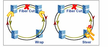
Figure 3 Wrapping and Steering Protection in
RPR
Wrapping and steering offer different tradeoffs. In general,
wrapping protection is faster than steering. However, both wrapping and
steering are guaranteed to occur within 50 msecs. Wrapping, however, has several drawbacks
compared to steering. It incurs more delay/longer path on ring, a double hit
when failure is restored and ring de-wraps and is less bandwidth
efficient. On the other hand,
broadcast/multicast support in RPR is the same under wrapping protection while
steering protection requires special handling. Finally, as a point of
comparison, we note that wrapping protection in RPR is very similar in concept
and operation as line-switching in BLSR SONET rings which is discussed earlier.
Steering is very similar to a version of BLSR switching, which is used in large
intercontinental rings [31], to minimize the long paths that arise with
wrapping.
Emerging Optical Transport Network Services and Solutions
Last few years have witnessed significant activity in the
optical transport arena. The work has resulted in significant new capabilities
in the optical transport layer and has effectively extended this layer from a
simple point-to-point physical transmission layer to a more complete end-to-end
network layer; see e.g., [68-75]. These innovations have included the
introduction of a number of automatic routing and signaling capabilities, to
the optical transport layer. These basic routing and signaling capabilities
enable a number of new applications as well as a variety of resiliency
mechanisms at this layer beyond the traditional SONET/SDH rings and 1+1 APS
discussed earlier.
The basic service provided by the optical transport layer is
physical transmission of bits. This basic service is provided in the form of
circuits such as DS1, DS3 and OCx channels. These
circuits could be viewed as the physical and conceptual equivalent of virtual
circuits in ATM and LSPs in MPLS. Once we realize
this correspondence, most of the logical circuit operations and capabilities,
such as resiliency mechanisms, from ATM and MPLS, for example, translate to
similar capabilities in the optical transport layer as well. There are, however, some important differences.
Equivalent of the MPLS Fast Reroute (FRR) and Shared Packet
Mesh are possible in the optical transport layer as well. These are often referred
to as Link and Path restoration respectively in the optical transport world
[78]. Just like the MPLS version, failures in link restoration are detected
locally at either of the two nodes adjoining the failed span. The physical
circuit is then rerouted on a path around the failure. The differences at the
optical transport layer, compared to MPLS restoration, are in failure detection
and the detailed mechanism by which circuits are rerouted. First, optical layer
restoration is concerned only with optical layer failures such as loss of
signal and bit error rate. These are usually detected by the underlying
physical layer monitoring mechanisms and no elaborate mechanisms such as OSPF
Hellos, MPLS OAM cells and like are necessary. Hence, failure detection is
simple and fast at the optical layer. Optical circuit reroute has one
significant difference to the corresponding logical circuit reroute mechanisms.
Note that in the case of optical layer, we are concerned with physical circuits
and not logical circuits. Hence, a reroute implies that physical connections
within the optical switch (or cross-connect as they are usually referred to)
need to be re-established at each switch on the reroute path. This is in
contrast to logical circuits in ATM and MPLS, where logical circuits are routed
based on logical labels which can be pre-established on the original and
reroute paths and traffic can be switched onto new paths by simple operations,
such as re-labeling packets, at the ingress/egress or repair point switch alone.
The fact that connections need to be physically established at each
intermediate switch has significant implications on restoration signaling as
well as speed of restoration. For link
restoration at optical layer, signaling is needed on restoration path similar
to that for a connection setup in the first place. Some of the drawbacks, as
far as speed of restoration, of having to physically establish connections at
intermediate switches can be overcome by pipelining the connection setups [72].
Path restoration at the optical layer works similarly to the
MPLS shared packet mesh discussed above. Failures are detected at the endpoints
of the circuit and communicated to the head-end, which switches the circuit to
a new end-to-end path. When the new path is completely disjoint with the
original connection path, failure isolation is not necessary. It is simply
sufficient to know that a failure occurred on the primary path. If we desire to
reuse some part of the original path in the new route, immediate failure isolation
becomes necessary that imposes further requirements and complexity in the
solution and would slow down the recovery.
Both link and path restoration for the optical transport
networks have similar performance characteristics in terms of restoration time
and capacity efficiencies, to their MPLS counterparts. A detailed analysis is
presented in [78]. In general, restoration times in the range of 50 to few 100 msecs are achievable with these mechanisms. Also, in terms
of capacity, significant savings are possible compared to SONET rings and 1+1
type mechanisms. Studies in several real service-provider networks [78] suggest
that optimized forms of the link and path restoration mechanisms can achieve
capacity savings of up to 45% over simple 1+1 mechanisms.
As a final point of comparison to the MPLS/ATM resiliency
mechanisms, the control plane plays an important and larger role in the above
emerging optical layer resiliency mechanisms. This is
evidenced, for example, by the need for explicit signaling on the reroute path
after the failure. Also, the control plane topology in optical transport
networks may or may not coincide with the user plane topology unlike
contemporary ATM/MPLS networks where there is a one-to-one correspondence. This
may be either by particular implementation or indeed by a deliberate design to
separate the control and user plane. This introduces several additional issues
in optical transport networks, see eg., [4,77]. It suffices to say that high resiliency and fast
recovery is also a key requirement for the control plane, considering the
potential impact on tremendous amount of data delivery in the optical transport
network should the control plane fails.
Earlier discussions on the emerging IP/MPLS solutions are clearly
excellent candidates for this control plane application.
Recommendations Based on IntelliGrid Architecture Requirements
In this section, we have reviewed resiliency services in
various existing and emerging network technologies that have been developed or
proposed for supporting needs by various applications. Selected emerging solution techniques have
been described and contrasted with some current services available from
physical to transport protocol layer.
Traditionally Utilities have been relying on SONET/SDH
protection for mission critical services, e.g. SCADA. This could well be
changed with the emergence of the IP/MPLS-based a cost-effective alternatives.
This is particularly true given the wide range of performance/ cost trade-offs
afforded by IP/MPLS based solutions as depicted in Table 1. Different IP/MPLS
based solutions can exist in the same IP network fabric which support an
integrated set of IntelliGrid Architecture services with a diverse range of QoS/survivability
requirements, e.g. ranging from mission critical real-time measurement ones
(which probably require 1+1 or fast local/shared-mesh re-route types of scheme)
and the less stringent need of off-line, non-real-time data processing for
which IP route recomputation/RSVP-TE based
restoration may suffice.
References
[1] ITU-T Recommendations G.114, One-way transmission time,
May, 2000.
[2] Gerald Blakowski and Ralf
Steinmetz, "A Media Synchronization Survey: Reference Model,
Specification, and Case Studies" IEEE JSAC Vol
14, No. 1, Jan. 1996.
[3] FCC reporting requirements, CC Docket 91-273.
[4] A.B. Sripad et.al, “Signaling Communications Network Architecture for
Service Intelligent Optical Transport Networks”, BLTJ, Vol. 8, Issue 2, 2003.
[5] Debanjan Saha , "Converging
Optical and IP: Can GMPLS Take Control?",
Communication Systems Design, Feb, 2002.
[6] A.K. Jain, editor, Intelligence in optical networks,
IEEE Communications Magazine, Volume: 39, Issue: 9, Sep 2001.
[7] V. Cardellini, M. Colojamni and P.S. Yu, "Load Balancing on
Web-server systems", IEEE Internet Computing Magazine, May/June Issue,
1999.
[8] M. Rabinovich and O. Spatscheck ,
Web caching and replication, Addison
Wesley, 2002.
[9] Chad M. Steel, "Building
a Multisite Web Architecture", IEEE Internet
Computing Magazine, Vol. 6, No. 5, Sept./Oct 2002
issue, p.g. 59-66.
[10] Douglas E. Comer, Internetworking with TCP/IP Vol.1:
Principles, Protocols, and Architecture, 4th edition, Prentice Hall,
2000.
[11] The Internet Engineering Task Force, http://www.ietf.org/
[12] J. Moy, “OSPF Version 2”,
IETF RFC 2328, April 1998.
[13] ITU-T Recommendation I.630, ATM protection switching,
2/99
[14] ATM Forum, Private Network-Network Interface
Specification V1.1 (PNNI 1.1), April 2002.
[15] ANSI/ IEEE Standards 802.1D, Media Access Control (MAC)
Bridges, 1998.
[16] John Proakis, Digital
Communications, 4th edition, McGraw-Hill, 2000.
[17] Raymond Steele and Lajos Hanzo (editors), Mobile Radio Communications, Wiley, John
& Sons, 1999.
[18] Charles E. Perkins, Sherman R. Alpert, With Bobby Woolf, Mobile IP : Design Principles and Practices, Addison-Wesley,
1997.
[19] Charles E. Perkins, Charles Perkins, Ad-Hoc Networking,
Pearson Education, 2000
[20] S. Nanda et.al,
"A Retransmission Scheme for Circuit-Mode Data on Wireless. Links,"
IEEE Journal of Selected Areas in Communications, Vol. 12, No. 8, pp.
1338-1352, October 1994.
[21] F. Khan et.al, "TCP Performance over CDMA2000 Radio Link
Protocol", IEEE Vehicular Technology Conference, 2000.
[22] CDMA Development Group, 3G-CDMA 2000 Technology, http://www.cdg.org/technology/3g.asp
.
[23] The 3rd Generation Partnership Project (3GPP), http://www.3gpp.org/ .
[24] The Third Generation Partnership Project 2 (3GPP2), http://www.3gpp2.org/ .
[25] Timo Halonen,
Juan Melero, Javier Romero Garcia, GSM, GPRS and EDGE
Performance: Evolution Toward 3G/UMTS, Wiley, John & Sons, 2002.
[27] ITU-T G.803: Architecture of Transport Networks Based
on the Synchronous Digital Hierarchy (SDH), March 2000.
[28] Telecordia GR-499-CORE, “Transport System
Generic Requirements (TSGR), Issue 2, Dec. 1998.
[29] Telecordia GR-1400-CORE,
“SONET Dual-Fed Unidirectional Path Switched Ring (UPSR) Equipment Generic
Criteria”, ISSUE 2, January, 1999.
[30] Telecordia GR-1230-CORE,
“SONET Bidirectional Line-Switched Ring (BLSR) Equipment Generic Criteria”,
Issue 4, December 1998.
[31] ITU-T G.841, “Types and Characteristics of SDH Network
Protection Architectures”, October, 1998.
[32] J. Warland, "Communication
Networks, a First Course", Publisher: Prentice Hall, 1991.
[33]T. Strayer and A. Weaver,
"Evaluation of transport protocols for real-time communications",
Technical Report TR-88-18, Department of Computer Science, University of
Virginia, Charlottesville, VA., 1988.
[34] Sami Iren,
Paul D. Amer and Phillip T. Conrad, "The
Transport Layer: Tutorial and Survey", ACM Computing Surveys, Vol. 31, No. 4,
Dec. 1999.
[35] R. Stewart et al, "Stream Control Transmission
Protocol," RFC 2960, IETF proposed standard, October 2000.
[36] L. Ong et. al,
"Architectural Framework for Signaling Transport," IETF RFC 2719, Oct 1999.
[37] L. Ong, "SCTP -- an executive
summary", http://www.sctp.org/sctpoverview.html
[38] Ivan Arias Rodriguez, "Stream Control Transmission
Protocol: The design of a new reliable transport protocol for IP
networks," http://www.sctp.org/IvanAriasRodriguezMastersThesis.pdf
.
[39] "SCTP for Beginners," http://tdrwww.exp-math.uni-essen.de/inhalt/forschung/sctp_fb
.
[40] Randall R. Stewart, Lyndon Ong,
Ivan Arias-Rodriguez, Kacheong Poon,
Phillip T. Conrad, Armando L. Caro Jr., Michael Tuexen, "Stream Control Transmission Protocol (SCTP)
Implementer's Guide", IETF draft, October 2002 (work in progress).
[41] Randall R. Stewart, http://www.sctp.org
.
[42] Randall Stewart, Qiaobing Xie and Mark C. Allman , Stream Control
Transmission Protocol (SCTP): A Reference, Publisher: Addison-Wesley, 2001.
[43] M. Tuexen, http://www.sctp.de
[44] Armando L. Caro Jr., Janardhan R. Iyengar, Paul D. Amer, Gerard J. Heinz, Randall R. Stewart, "Using SCTP
Multihoming for Fault Tolerance and Load
Balancing," SIGCOMM 2002 Poster, August 2002,
Abstract in Computer Communication
Review, 32(3):23, July 2002.
[45] Armando L. Caro Jr., Janardhan R. Iyengar, Paul D. Amer, Gerard J. Heinz, Randall R. Stewart, "Threshold
Recovery Mechanism for SCTP," SCI
2002, July 2002.
[46] Armando L. Caro Jr., Janardhan R. Iyengar, Paul D. Amer, Gerard J. Heinz, Randall Stewart, "SCTP Failure
Detection and Recovery: Smoother Transitions and Increased Throughput",
Proc. SCI2002, July 2002.
[47] Janardhan R. Iyengar, Armando L. Caro Jr.,
Paul D. Amer, Gerard J. Heinz, Randall R. Stewart,
"Making SCTP More Robust to Changeover,” Technical Report TR2003-01,
Computer and Information Sciences Department, University of Delaware, 2002.
[48] Janardhan R. Iyengar, Armando L. Caro Jr.,
Paul D. Amer, Gerard J. Heinz, Randall R. Stewart,
"SCTP Congestion Window Overgrowth During Changeover," SCI 2002, July 2002.
[49] A. Jungmaier, M. Schopp and M. Tuxen,
"Performance Evaluation of the Stream Control Transmission Protocol,"
in the Proc. of Joint IEEE ATM Workshop
2000", Heidelberg, Germany, June
2000.
[50] A. Jungmaier, E.P. Rathgeb, M. Schopp and M. Tuxen, "SCTP - A multilink end-to-end protocol for
IP-based networks," in
the Procs. of Joint IEEE ATM Workshop
2000", International Journal of Electronics and Communications, Vol 55, No. 1, pg. 46-54, 2001.
[51] A. Furquan and Ajay Sathyanath, "STEM: Seamless Transport Endpoint
Mobility," submitted to ACM SIGCOMM, Sept, 2003.
[52] V. Sharma, and F. Hellstrand,
“Framework for MPLS-based Recovery”, IETF RFC 3469, Feb. 2003.
[53] ITU Draft Recommendation, “Protection Switching for
MPLS networks”, Y.1720, Nov. 2002.
[54] Ramesh Nagarajan, M. Akber Qureshi and Y.T. Wang, “Resilient Packet Mesh (RPM): A
Platform of Reliable Packet Transport Technologies for IP/MPLS Networks,”
submitted for publication, 2003.
[55] Ramesh Nagarajan, M. Akber Qureshi and Y.T. Wang, "A Packet 1+1 Path
Protection Service for MPLS Networks," <draft-nagarajan-ccamp-mpls-packet-protection-00.txt>,
Mar. 2002
[56] P. Pang, and A. Atlas, “Fast Reroute Extensions to
RSVP-TE for LSP Tunnels”, draft-ietf-mpls-rsvp-lsp-fastreeoute-01.txt, May
2003.
[57] H. Liu et. al,
“RSVP-TE Extensions for Shared Mesh Protection”, draft-liu-mpls-rsvp-shared-protection-00.txt,
October 2002.
[58] Ajay Sathyanath et.al, "OSPF-TE Extensions for Shared Mesh
Protection<draft-sathyanath-ospf-mpls-shared-protection-00.txt>, Oct.
2002
[59] Z. Dziong et al., “Efficient
shared capacity path restoration in mesh optical networks,” In Proceedings of
NFOEC, September 2002, Dallas.
[60] IEEE Standard for Local and Metropolitan area networks
-- Common specifications Part 3: Media Access Control (MAC) bridges --
Amendment 2: Rapid Reconfiguration, 2001.
[61] Vipin Jain and Mick Seaman,
"Faster Flushing with Fewer addresses", contribution to IEEE 802.1,
standards meeting, Jan 1999.
[62] Mick Seaman, "High Availability Spanning
Tree," contribution to IEEE 802.1 standards meeting, Oct 1998.
[63] Mick Seaman, "Truncating Tree Timing,"
contribution to IEEE 802.1 standards meeting, Jan 1999.
[64] Mick Seaman, "Speedy Tree Protocol,"
contribution to IEEE 802.1 standards meeting, Jan 1999.
[65] Mick Seaman, "Loop Cutting in the Original and
Rapid Spanning Tree Algorithms," contribution to IEEE 802.1 standards
meeting, Jun
1999.
[66] Mick Seaman, "Rapid Spanning Tree Migration,"
contribution to IEEE 802.1 standards meeting, Nov 1999.
[67] IEEE 802.17 Resilient Packet Ring Working Group, http://grouper.ieee.org/groups/802/17/
[68] D. Awduche, et al, “ Multiprotocol Lambda Switching:
Combining MPLS Traffic Engineering Control with Optical Cross-connects” , IEEE
Communications Magazine, March 2001.
[69] Eric Mannie et.al.,
“Generalized Multi-Protocol Label Switching (GMPLS) Architecture”, IETF
draft-ietf-ccamp-gmpls-architecture-03.txt, Aug. 2002
[70] ITU-T G.7712, “Architecture and specification of data
communication network,” Oct 2002.
[71]
J. Manchester, et al., “The Evolution of Transport Network
Survivability”, IEEE Communication
Magazine, Vol. 37 No. 8, August, 1999
[72]
A. Banerjee, et al, “Generalized Multiprotocol Label
Switching: An Overview of Signaling Enhancements and Recovery Techniques”, IEEE Communications Magazine, July 2001.
[73]
S. Ramamurthy and B. Mukherjee,
“Survivable WDM Mesh Networks, Part I –Protection”, IEEE Infocom 1999.
[74]
A. Fumagalli and L. Valcarenghi,
“ IP Restoration vs. WDM Protection: Is There an Optical Choice”, IEEE Network,
Nov., 2000.
[75]
B. Rajagopalan, et al., “IP over
Optical Networks: Architectural Aspects”, IEEE Communications Magazine, Sept,
2000.
[76]
B. Doshi, et al., “Optical Network
Design And Restoration”, Bell Labs Technical Journal, Volume 4, No. 1, 1999.
[77] Gary P. Austin et.al, “Fast,
Scalable and Distributed Restoration in General Mesh Optical Networks”, BLTJ, Volume 6, Number 1, Jan - Jun
2001.
[78] Carol Janczewski, et.al, “Restoration Strategies in Mesh optical Networks:
Cost, Performance and Service Availability”, NFOEC 2002 Conference Proceedings.
[79] Zbigniew Dziong
et.al, “Efficient Capacity Sharing in Path
Restoration Schemes for Meshed Optical Networks”, NFOEC 2002 Conference Proceedings.
[80]
R. Doverspike, “ A Multi-Layered Model
for Survivability in Intra-LATA Transport Networks”, IEEE Globecom,
1991.
[81]
K. R. Krishnan, R.D. Doverspike, and C.
D. Pack, “Improved Survivability with Multi-Layer Dynamic Routing”, IEEE
Communication Magazine, July, 1995
[82]
P. Demeester, et al., “Resilience in
Multilayer Networks”, IEEE Communication Magazine, Vol. 37 No. 8., August,
1999.
[83]
D. Papadimitriou, et al., “Packet-Optical Escalation Strategies”,
Internet Draft, draft-pbh-packet-optical-escalation-02.txt, Nov., 2001, work in
progress.
[84]
K. Owens, et al., “Network Survivability Considerations for
Traffic Engineered IP Networks”, Internet Draft, draft-owens-te-network-
survivability-01.txt, July, 2001.
[85]
F. Touvet and D. Harle,
“Network Resilience in Multilayer Networks: A Critical Review and Open Issues”,
P. Lorenz (Ed.): ICN 2001, LNCS 2093, pp. 829-837, 2001.
[86]
Y. Ye, et al., “On Joint Protection/Restoration in IP-Centric
DWDM- Based Optical Transport Networks”,
IEEE Communication Magazine, June, 2000.
[87] D. Saha
and N. Ghani, editor, IP-Optical Integration,
July/August 2001 issue of IEEE Network.
[88]
User Network Interface (UNI) 1.0 Signaling Specification, OIF
Forum, http://www.oiforum.com , Oct 2001.
[89] C. Chigan, G. Atkinson, R. Nagarajan,
T. G. Robertazzi, “On Joint Restoration of IP-over-Optical Networks”, proceedings of
18th annual National Fiber Optic Eng. Conference, Dallas, TX, Sept, 2002.
This page is
intentionally left blank.
|
