|
The amount of data
being collected or capable of being collected is increasing exponentially. This
rapid expansion of data retrieval results from the fact that more field devices
are being installed and that these field devices are becoming more
"intelligent" both in what power system characteristics they can
capture, and also in what calculations and algorithms they can execute which
result in even more data.
As distribution
automation extends communications to devices on feeders, as substation
automation expands the information available for retrieval by substation
planners, protection engineers and maintenance personnel, and as more power
system asset information is stored electronically in Geographical Information
Systems and AM/FM systems, even more varieties and volumes of data will need to
be maintained and managed.
Data management is
a complex issue, encompassing many aspects of data accuracy, acquisition and
entry, storage and access, consistency across systems, maintenance, backup and
logging, and security. These are discussed in the following sections.
Data management
must address a complex set of issues that include the following services:
·
Validation of source data and data exchanges
·
Ensuring data is up-to-date
·
Management of time-sensitive data flows and
timely access to data by multiple different users
·
Management of data consistency and
synchronization across systems
·
Management of data formats in data exchanges
·
Management of transaction integrity (backup and
rollback capability)
·
Management of the naming of data items
(namespace allocation and naming rules)
·
Data Accuracy
·
Data Acquisition
·
Data Entry
·
Data Storage and Access Management
·
Data Consistency across Multiple Systems
·
Database Maintenance Management
·
Data Backup and Logging
No single
cross-industry technology addresses all of these issues, but multiple solutions
and best practices are available for different aspects.
The first
principle of IntelliGrid Architecture architectural vision is the principle of abstract
modeling techniques, as expressed in the following quote:
“There are limits to human ability to
understand [truly complex systems] and to solve large sets of system
equations. The problem must be broken
down or divided into a series of smaller problems that can be solved. Modeling is one of the proven and
well-accepted engineering techniques that simplify the system, so that we can
better understand the system being developed.
System simplification is achieved through the introduction of levels of
abstraction, which allow the modeler to focus on one particular aspect of the
system at a time.”
So that the
abstractions used in IntelliGrid Architecture analysis may be more clearly understood, the
IntelliGrid Architecture has been developed and refined using an international
standard for architecture design call the “Reference Model for Open Distributed
Processing” framework, RM-ODP. RM-ODP is the reference model for defining open,
distributed software system architectures. It was developed with extensive
input from the technical community and represents a substantial body of
knowledge. It was therefore the natural selection as a means for developing and
expressing IntelliGrid Architecture.
RM-ODP is a formalized approach to developing
abstract models of system functions, which helps to ensure that all
requirements are identified and analyzed before the functions are
implemented. It breaks down the analysis
and description of an architecture into five largely complimentary
viewpoints. Each viewpoint answers a
different set of questions. These
viewpoints are summarized in the following table.
|
Table 2 Summary of RM-ODP
Viewpoints
|
|
Viewpoint
|
Question
|
Contains
|
|
Enterprise
Viewpoint
|
Who is
involved?
|
Information
about the various participants and functions implemented in the energy
industry
|
|
Information
Viewpoint
|
What
information must be exchanged?
|
Models of
information exchanged, agreements between parties, and roles and
relationships that underpin the data of industry functions
|
|
Computational
Viewpoint
|
How is this
information going to be exchanged?
|
The mechanics
related to information exchange i.e. a discussion of the interfaces required.
|
|
Engineering
Viewpoint
|
Where is the
information located and where will it be sent?
|
The
configuration for where to physically deploy clients, servers, databases, and
subsystems in terms of what component is deployed on which network for
example. This view describes the
partitioning of a solution and where the pieces reside and closely
corresponds to IntelliGrid Architecture Environments.
|
|
Technology
Viewpoint
|
Which
technologies and best practices are to be used to accomplish this?
|
Actual
technology and best practice solutions that can be used to carry out the
functions
|
It is important to note
that RM-ODP is a framework for describing architectural
views, and provides a reference model for developing architectures, but it is
not an architecture itself.
In the IntelliGrid Project, the main purpose for using RM-ODP was to ensure that all architecturally
significant requirements were identified for existing and future power
system operations functions.
The Unified Modeling
Language, UML, provided both the abstract language and computer tools that the
team employed for expressing its analysis within the RM-ODP framework. These two approaches, RM-ODP and UML, complemented each other in the
development of the architecture:
·
As a framework, RM-ODP is very abstract and does not call out the
use of a particular notation nor does it have tools that are directly linked to
its concepts.
·
UML has very good tools available, but is not an
architecture standard and is not usually used at the same level of scope as RM-ODP.
The two can be used
together because they are complementary and support similar levels of
abstraction. Even though there is not a direct match between RM-ODP terms and UML terms, constructs can be
developed in UML to realize RM-ODP
concepts. The widely available UML tools
can then be used to create the diagrams and underlying database that is
necessary for understanding the complex interactions of power system functions
across multiple areas. Both are useful
standards as both embody the following concepts:
·
UML is a technology neutral way of specifying use
cases, data, and software components.
RM-ODP separates technology specifics into the
Technology View. IntelliGrid Architecture uses UML to
specify a technology neutral architecture.
·
UML is a deployment neutral way of specifying
data and software components. RM-ODP separates deployment specifics into the
Engineering View. IntelliGrid Architecture uses UML to
specify deployment neutral architecture that can be applied to a variety of
environments.
In conclusion, UML and
RM-ODP have enabled IntelliGrid Architecture Team to design an
architecture that is flexible and can be applied to a diverse set of
environments and technologies. UML and
RM-ODP provide a standard language so that the
design of the architecture can be communicated to others.
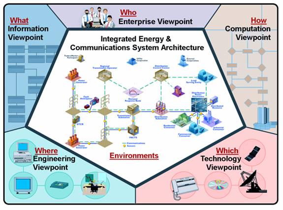
Figure
3: Integrated Energy and Communication
Systems Architecture (IntelliGrid Architecture) RM-ODP Model
The abstract
modeling process used during IntelliGrid Architecture project leading from RM-ODP to the final architecture is outlined below.
In general, the UML concept of “Use Cases” was used to capture stakeholder
requirements, and a UML tool called Magic Draw was used to generate diagrams
that expressed the architecture in the five RM-ODP viewpoints.
1.
UML Use Case
Template: The highest level UML construct for describing a function is the
Use Case, which can map more or less into the RM-ODP Enterprise Viewpoint. Since not many people
have UML tools, people in the IEC and IEEE have been describing functions using
a “Use Case Template”. A Use Case
Template is a MS Word document that captures the UML concepts of Actors, Roles,
Associations, Classes, and other UML constructs. This Use Case Template could
then be used to enter the information into a UML tool, like Rational Rose or
Magic Draw. The Use Case Template doesn’t have any standard format, but usually
includes sections to:
·
Describe the function in narrative form
·
Identify the Actors and Information Exchanged
·
Identify the steps involved in exchanging
information between Actors.
2.
UML Use Case
Template to IntelliGrid Architecture Domain Template: In IntelliGrid Architecture project, the team renamed
the Use Case Template the “Domain Template” and modified it in a number of
ways:
·
Added a number of additional fields and
requirements beyond those of a traditional UML Use Case in order to capture
more RM-ODP concepts, such as policies and contracts
between Actors.
·
Added the RM-ODP concept of Common Services (services that
can be used by many different functions) as well as a spreadsheet to capture
common requirements across all Use Cases.
·
The IntelliGrid Architecture team identified a number of common
Environments, discussed later in section 2.
Each environment has different configuration, performance, security and
data management requirements. Each
“step” in a Use Case was assigned to a particular environment for use later in
determining appropriate technologies to use for that step.
3.
Importing Domain
Templates into UML Tool: Domain
Experts filled out Domain Use Cases using the Domain Template. These were then
imported automatically into the Magic Draw UML tool. The resulting diagrams
became a tool for IntelliGrid Architecture team to further analyse the requirements captured
in the Domain Templates.
4.
Results from the
RM-ODP
Analysis Become the Technology and Deployment Neutral Reference Architecture:
As stated above, RM-ODP is a reference model for defining a distributed
system architecture for a particular software function. However, the purpose of
IntelliGrid Architecture project is not to develop a single architecture for one specific
function; the purpose of IntelliGrid Architecture project is to develop a Reference Architecture
for all
power system functions. The
relationships captured in the UML tool can be used as a database for
determining the appropriate approach to any power system communications
problem. In this sense, the database
becomes the architecture.
Through analysis
of the Domain Use Cases, the team identifies a limited set of common functions
necessary to implement each Domain Use Case. In order to capture this common
functionality IntelliGrid Architecture team derived a set of Abstract Use Cases. The Abstract Use Cases are:
·
Integration of Enterprise Management – The
integration of software and hardware component management functions with power
system functions
·
Integration of Utility Wholesale and Retail
Market Operations - The integration of market operation functions with power
system functions
·
Device Integration – The integration of
heterogeneous power system devices.
·
Application Integration – The integration of
heterogeneous power system applications to meet operational needs.
·
Data Integration – The integration of
heterogeneous power system data to meet analytic needs.
·
Security Integration – The integration of
security across multiple domains.
The process of
using Domain Use Cases to derive Abstract Use Cases is a key simplification
used by IntelliGrid Architecture Team. That is, the
Team realized that it would be impossible to analyze all conceivable Domain Use
Cases within a limited timeframe and budget.
Instead, the Team realized that they had to pick a much smaller set of
“architecturally significant” Domain Use Cases. These “architecturally significant” use
cases were then used to create more generalized Abstract Use Cases as
illustrated in Figure 0‑4.
Figure
0‑4 Abstract
Use Cases from Domain Use Cases
This second set of
use cases is abstract because they are not tied to any particular utility
function. However, the Abstract Use
Cases are more useful in deriving detailed components of an architecture
because they allowed the Team to abstract away the specifics of Domain Use
Cases and permitted the team to focus on the commonality and diversity of all
Domain Use Cases. The commonality is
expressed as a set of common modeling elements and the diversity is expressed as
a set of environments and technologies as shown in Figure 5:
Figure
5 Environments from Requirements
The abstract set
of use cases is illustrated in Figure6 below:
Figure6 The IntelliGrid Architecture Abstract Use Cases
This section
discusses the derivation of the Abstract Use Cases from the Domain Use Cases.
ADA
Advanced
Distribution Automation (ADA) involves software applications in the control
center supplemented by applications and functions implemented in field
equipment. The control center applications provide the global analysis of the
distribution system state and capabilities and are the overarching functions in
control of distribution system operations, while the field equipment
applications provide local information and control.
The ADA
applications in the control center rely heavily on data from many different
sources, and going to different systems:
·
SCADA system for real-time data from field
equipment and control command to field equipment, including both substations
and feeder equipment
·
DER
equipment, either directly or indirectly through DER Aggregators
·
Energy Management System (EMS) for transmission information and
·
Geographical Information System (GIS) and/or Automated Mapping and Facilities
Mapping (AM/FM) systems for power system facilities data and physical
connectivity data
·
Customer Information System (CIS)
·
Work Management System (WMS)
·
Distribution Planning Systems
·
Market Operations systems
The primary
architectural requirements for ADA are focused on data management. Correct,
available, and timely data are crucial to the ADA function operating properly.
However, since data comes from many different sources and since the systems
acting as these sources usually are provided by different vendors, the
coordination, synchronization, integration of systems, and mapping of data
elements across these systems is a major problem.
In addition,
because real-time control of the power system is a major aspect of ADA, both
security and network management are critical to safe and reliable operation of
the power system. Therefore the main requirements are those associated with the
“Critical Operations DAC” Environment and the “Intra-Control Center”
Environment ( a complete list of IntelliGrid Architecture Environments can be found in Appendix
E):
1.
Security Requirements
·
Provide Authorization Service for Access Control
(resolving a policy-based access control decision to ensure authorized entities
have appropriate access rights and authorized access is not denied)
·
Provide Information Integrity Service (data has
not been subject to unauthorized changes or these unauthorized changes are detected)
·
Provide Audit Service (responsible for producing
records, which track security relevant events)
·
Provide Credential Renewal Service (notify users
prior to expiration of their credentials)
·
Provide Security Policy Service (concerned with
the management of security policies)
·
Provide Single Sign-On Service (relieve an
entity having successfully completed the act of authentication once from the
need to participate in re-authentications upon subsequent accesses to managed
resources for some reasonable period of time)
·
Provide User Profile and User Management
(combination of several other security services)
·
Provide Security Discovery (the ability to
determine what security services are available for use)
2.
Network and System Management Requirements
·
Provide Network Management (management of media,
transport, and communication nodes)
·
Provide System Management (management of end
devices and applications)
3.
Data Management Requirements
·
Support the management of large volumes of data
flows
·
Support keeping the data up-to-date
·
Support extensive data validation procedures
·
Support keeping data consistent and synchronized
across systems and/or databases
·
Support timely access to data by multiple
different users
·
Support frequent changes in types of data
exchanged
·
Support management of data whose types can vary
significantly in different implementations
·
Support specific standardized or de facto object
models of data
·
Support the exchange of unstructured or
special-format data (e.g. text, documents, oscillographic data)
·
Provide discovery service (discovering available
services and their characteristics)
·
Provide conversion and protocol mapping
Therefore, if one
abstracts from these functions, one can say that ADA from an architectural
perspective requires:
·
Integration of many different systems developed
by different vendors for differing requirements
·
Development of a platform that spans many
different systems, applications, and databases
·
Management of data across multiple systems,
including data consistency and synchronization with short timeframes
·
A system to manage configuration and change
·
Security integration across multiple security
domain
Customer Interface
With the advent of
deregulation, the interface between ESP and consumer has become more important,
because customers can (and have) switch(ed) energy providers and because they
can now be an additional source of revenue if new energy services can be sold
to them, or if the utility rights within the customer premises can be used to
sell access to other businesses.
The expansion of
system operations coordination and control down to the end user level creates
one of the key justifications for IntelliGrid Architecture. An enterprise-wide architecture such
as IntelliGrid Architecture offers a tremendous opportunity for improved operational efficiency,
improved control of customer processes based on supply system conditions, use
of customer-owned and operated generation and power quality improvement
technologies as part of overall system management and to achieve the required
levels of reliability and power quality at the end user level. In as far as the other side of the equation,
implementation of load control/demand response programs provides utilities with
another key tool to ensure power system stability and security.
Applications
related to customer interface must be coordinated closely with distribution
automation and distributed resource applications, as well as market
operations. Key applications include
·
Real time pricing
·
Load management
·
Residential customer applications, such as load
control in response to real time pricing incentives
·
Direct customer energy management and load
control during system emergencies
·
Automatic evaluation of and recommendations for
increasing energy efficiency based on profiles of the customer site and loads
·
Control and performance evaluations for
residential generation
·
Power quality assessments and control.
Also critical are
commercial and industrial (C&I) applications such as commercial customer
participation in energy markets through aggregation of backup generation and
energy management, participation in ancillary services (such as volt/var
control, harmonic control, and reserve generation), real time commercial
facility power quality assessment solutions integrated with the distribution
system operation and integration of real time information concerning system
power quality and reliability.
By nature,
customer interface/consumer services applications share close coordination with
distributed automation, distributed resource, and market operation
applications. The current status of
utility industry restructuring, as well as the current state of technology,
necessitate that many consumer service applications rely on distributed
automation and distributed energy applications and their underlying
communications requirements.
Furthermore, consumer interface is playing a key role in market
operations where customer load and/or onsite generation may be aggregated and
utilized to bid into energy markets and key customers may have sufficient
requirements for power to play a role in bulk power trading, scheduling, and
supply scenarios.
The range and
scope of customer interface/consumer service applications is complex and
growing. The possibility of customers
and ESPs managing load down to the appliance level could generate requirements
with a level of granularity not seen in any other domain. However, at the present time and taking both
short and long term scenarios into consideration, the domain analysis covered
three key applications:
·
Real time pricing
·
Utility administered load control
·
Consumer side data collection
RTP is important because it requires
communication between the customer and the ESP in terms of the ESP providing RTP signals to the customer and the customer
potentially providing bids and forecasts back to the ESP.
Quality of service including high availability and timeliness of data is
crucial. There are large numbers of
customer with sensitive information on pricing and usage; therefore security is
a key consideration. Since future power
system operating scenarios will undoubtedly involve more two-way communication
with the customer and the ESP
as well as increased customer sensitivity to pricing data, this is a
significant area for requirements analysis.
Utility
administered load control is where, instead of responding to price signals, the
signal comes directly from the ESP
to control customer loads. This
application covers a wide range of issues, especially security across
organizational domains and the need for two-way communications to confirm load
control actions for future advanced demand responsive systems.
Data collection
from the consumer side is seen as critical to facilitate more active
involvement by customers in the interface to and participation in market
operations and energy management. In
terms of power quality monitoring, the information is intermittent and
sometimes infrequent, but timely, communication and notification is very
important when events do occur.
Analysis of the
requirements associated with these requirements showed trends that were common:
·
Database integration and management is critical,
with utilization on both customer and ESP systems and even inside one system, with
multiple installations and different purposes.
For instance, for ESPs, there may be one database for customer billing
data, a database for pricing data, and a separate database for operational
data, i.e., customer participation in RTP or load control programs. Some of the data requirements are low in
volume (such as usage data) while others may be high in volume with detailed
information (such as power quality monitoring data).
·
There are multiple levels and requirements of
security and in addition to ESP
security issues, which are significant and substantial, there are issues
relating to the privacy of customers and desire to secure customer data and
facilities from unauthorized access and cyber attack. Securing the consumer interface frequently
requires different technologies than securing ESP-specific functions.
·
Communication and bandwidth requirement run the
gamut from telephone line to wireless to fiber.
Much equipment related to customer metering has not been upgraded to
take advantage of the state of the art, so legacy systems and disparate data
transportation mechanisms require an enterprise-level approach to systems
integration.
·
Customer services factor in financial
transactions. Much as with market
operations, money will be changing hands in applications such as power trading
and real time pricing. This brings into
play a different set of considerations than the traditional ESP operations.
·
The amount, scope, and time frame for
transactions are constantly evolving. As
more customer services are identified and as the technology matures and
emerges, the far reaching vision of a consumer portal, where a customer can
manage every aspect of their interface with the electrical grid and energy
usage, comes into play. This
necessitates the ability to add and address requirements for technologies that
are still in the development stage.
As can be seen,
while this domain has some specialized requirements, it shares requirements
with several other domains regarding wholesale and retail market operations
integration, application integration and data integration.
Wide Area Measurement and Control
The goal of Wide
Area Measurement and Control (WAMAC) is to synchronize and coordinate the
measurements of the state of the power system across large geographic areas, to
model and simulate system behavior in real-time, to anticipate fast-changing
system conditions, and to support multiple automation and control response
capability. The core functions of WAMAC include:
·
Synchrophasor calculation –Historically, voltage
and current phasors were measured against a local reference angle, complicating
the state estimation process of determining system wide phasors against a
common reference. Synchro-phasors are measured over a wide area against a
common reference angle and the information can be made widely available, which
will greatly simplify the state estimation problem.
·
Dynamic model update – WAMAC depends on accurate
models of the state of the system and the capability of the system to respond
to control actions. WAMAC requires accurate and timely updated models.
·
Real time state measurement and security
assessment – WAMAC functions include steady-state and dynamic analyses and risk
assessment that consider multiple set of independent and dependent
contingencies while applying probabilistic models of power system components.
The increased dimension and limited time intervals of these function creates
communication and computational challenges.
·
Real-time proactive/preventive dynamic control –
The decision making for the proactive/preventive dynamic control actions
implies analyses of multiple complex scenarios with possible conflicting
results. Fast simulation based on adequate modeling is an imperative
requirement. The timely and reliable implementation of these control actions
poses communication challenges for the WAMAC system.
·
Emergency control – Emergency control focuses on
preservation of power system operations without endangering the power
equipments. WAMAC should perform multiple remedial control schemes in adaptive
and timely manners providing integrity and generation-load balances of power
system areas.
·
Automated restoration – The ideal goal of
restoration is fully automated self-assembly of the entire power system. In
this case, WAMAC must coordinate the re-synchronization of separated
transmission lines, reconnection of affected distribution systems and customer
loads. WAMAC must interact with Advanced Distribution Automation functions to
leverage DERs in support of the restoration actions.
The power system
is the largest and most complex system created by man. As it has grown, human
management and control of it has proved quite challenging. Moving to the future, an information based
Wide Area Measurement And Control system will be needed to provide
instantaneous (10s of ms) measures of the system conditions to enable dynamic
modeling of the various complex power system phenomena. Such requirement
involves gathering and coordinating the data from large areas and various
organizations. The creation of synchrophasors provides the technical means to
make unified measurements over a wide area.
The implementation over of wide area communications allows consolidation
of these measurements through what is known as Phasor Data Concentrators
(PDCs). The devices that create the synchronized measurements, commonly known
as Phasor Measurement Units (PMUs), often provide synchronized measurements
that span organizational and divisional boundaries. Organizational boundaries
would include sharing aggregated data between utilities. Data communication must only occur with those
entities authorized to receive the synchronized data. As much of the synchronized data indicates
instantaneous system state, this communication of this data must be secure for
some period of time as it could be used by power marketers in the pricing of
electricity. The present NERC agreement
between organizations that share data requires confidentiality of operations
data for 8 days. Divisional boundaries
include the issuance of control information to distribution companies and can
potentially migrate directly to direct load control in the home. This type of application requires the utmost
in secure and authenticated communications.
To validate
existing system models and to dynamically update them is another challenge for
WAMAC. Connectivity of the areas affected by a power system event needs to be updated
in the model in real time. Input data such as specific impacts of load inertia
on frequency-related phenomena or impacts of saturated devices are critical to
the model. Lack of these critical data is an issue to WAMAC and, as such, high
availability of the synchronized data is required.
WAMAC must
accomplish many complex decisions and control actions within milliseconds to
second time intervals. There are three security states in the power system
operations: normal, emergency and restorative. The timing requirements for each
of these states are different. The dynamics of loads, generation and system
topology drive the timing requirements for the normal state. Any decision made
when the system is in the normal state should be valid in the time interval
between the consecutive runs of the particular application. In the emergency
state, the time for the decision-making and its implementation is considerably
shorter than the normal state. In the emergency state, the power system
conditions could change dramatically in the 10s of millisecond range. The
amount of data that need to be processed by WAMAC is substantial in as much as
it is continually streamed. Failure to respond to the emergency conditions
could result in system instability and possibly lead to large scale blackouts.
The same timing requirement applies to the restoration actions due to the need
for simultaneous execution of control actions. Again, any control action need
to be secure and issued with the proper authority.
In the control
mode, WAMAC needs to coordinate the implementation of the power system state
machine. In the general case, an operational decision in power system
management consists of several control actions, each of which takes time to
finish. In many cases, a subsequent action depends on the successful completion
of the previous action. No harmful operation conditions should occur during the
intermediate steps.
To summarize, the
successful implementation of WAMAC relies on IntelliGrid Architecture to provide:
·
Automated information support/data aggregation
appropriate for the timing and complexity of the process to be controlled
o
Reliable, high-speed, secure, point to
multi-point communications
o
Automatic system configuration
o
Automated configuration and remote control of
executing devices or their modes of operations (settings)
o
High-speed application data access
o
Integration of different information systems
·
Secure information sharing among different
organizations
o
Authentication of control commands
o
Data confidentiality
·
Integration and coordination of centralized and
distributed intelligence
o
Integration of different control systems, such
as EMS, DMS and Market operation system
o
Cross-domain communications with Advanced
Distribution Automation applications
·
Utilization of modern information technologies to
solve data-overwhelm issue, to enhance data availability, and to provide modern
data visualization
Conclusion of Domain Use Case
Analysis
This section has
shown that in order to deploy the functionality describe in the Domain Use
Cases in an economical way, one has to deploy the functionality described in
one or more of the Abstract Use Cases.
However, besides deriving the Abstract Use Cases from Domain Use Cases,
one can also derive the Abstract Use Cases via a more theoretical
discussion. The following section
includes this discussion as well as analysis of the Abstract Use Cases for
derivation of the IntelliGrid Architecture.
On an abstract
level, one can state that IntelliGrid Architecture must support just two capabilities:
·
Provide support for the operation of existing
and future utility functions.
·
Provide support for the integration of existing
and future utility functions.
Note that support
for the operation of existing functions is known and currently implemented by
utilities. Note that support for the
operation of future functions is largely addressed by the development of new
applications and technologies. As IntelliGrid Architecture
is not an application or technology development project, this is out of scope. This leaves support for the integration of existing
and future utility functions as the primary issue to be solved by IntelliGrid Architecture. Also, since an architecture for non utility
specific functions will be driven by cross industry groups such as the W3C,
IEEE, or even major information technology vendors, IntelliGrid Architecture more narrowly focuses
on specializing these cross industry architectures to utility specific
functionality.
One can state that
integration issues related to utility specific activity are limited to:
A.
Integration of applications and data for
operational and analytic purposes.
B.
Integration of devices as well as hardware and
software services for operational and managerial purposes.
C.
Secure integration of applications, data, and
devices within a utility, between a utility and an energy market partner, and between
a utility and an operational partner.
The operational partner means an external entity that works with a
utility to meet operational as opposed to market driven goals.
The common terms
for Group A include:
I.
Application
integration
II.
Data
integration
The common terms
for Group B include:
III.
Device integration
IV.
Enterprise management
The common terms
for Group C include:
V.
Energy
Trading
VI.
Security Integration – especially security
across security domains
The IntelliGrid Architecture Team
believes that these six abstract use cases provide complete coverage of utility
specific functionality required for the complete analysis for comprehensive
architecture.
The goals of IntelliGrid Architecture Enterprise Architecture include:
·
Establish an architecture to integrate all of
the utility enterprise - from Energy Market partners to backend systems to
devices.
·
Enable comprehensive and unified views of the
utility enterprise to allow creation of new applications that can look across
the utility and focus on end-to-end profitability and reliability.
·
Establish Comprehensive Security Architecture
that accommodates integration of autonomous security domains.
·
Create
migration plan whereby legacy applications can be adapted to conform to the
IntelliGrid Architecture and new application can be non-disruptively added.
Figure 7 below portrays the different elements than need to be
integrated by IntelliGrid Architecture.
Figure 7 IntelliGrid Architecture Secure Enterprise Architecture
This section
describes the Abstract Use Cases in more detail and why these tasks play an
important part of enterprise integration and the development of higher-level
profitability and reliability focused analysis applications
Integration of Enterprise
Management and Power System Services
This section
describes the challenges facing the integration of Enterprise Management,
sometimes called communications System Management or Network Management, into
the power system.
In order to create
a truly reliable power system, IntelliGrid Architecture team needed to consider more than just
power system services. Modern utilities
monitor and control the power system via a vast network of
communication-enabled devices.
Traditionally, the data related to power system operation and
communication system operation has been treated independently, as illustrated
in Figure 8.
Figure
8 Enterprise Management and Power System Management Treated
Independently
However, operation
of the power system is now completely dependent on successful operation of the
communication system. It is clear that
in order to achieve a comprehensive view of end-to-end reliability one needs to
integrate communications system and power system analysis as shown below:
Figure 9 Integration of Enterprise and Power
System Management
System/network
management, also referred to as enterprise management, is the task of ensuring
that the systems and the network provide the required services with the
specified quality of service to the users and other systems. Most enterprise
management architectures use agent-manager relationships where the agents,
residing on the managed elements, provide management information, such as
alerts or performance measurements, to the manager.
The manager reacts
to these messages by executing one or more actions such as:
·
Operator notification
·
Event logging
·
System shutdown
·
Automatic attempts at system repair.
Management
entities also poll managed elements, automatically or upon user request, to
check the values of certain attributes of the managed device. Agents have
information about the managed devices in which they reside and provide that
information (proactively or reactively) to management entities within an
enterprise management system using a management protocol.
Typically,
enterprise management functions are performed on the following managed
elements:
·
Network devices such as routers,
switches, hubs, customer premises equipment and communication links;
·
Computing resources such as substation
automation systems and data concentrators; servers such as Market Transaction
Servers;
·
Software services such as SCADA, EMS, or GIS components, as well as database management
systems;
·
Service and business functions such as RTP customer pricing service, security and
operational policy servers; and
·
Storage area networks.
In IntelliGrid Architecture, the team
adds the power systems network-aware devices such as IEDs and RTUs to the
above.
The International
Organization for Standardization (ISO) has defined the following network
management functions for fault, configuration, accounting, performance and
security (FCAPS) management. Although defined for network management, these
functions can be generalized to systems and applications management.
Fault Management Function- Fault
management detects, fixes, logs, and reports network problems. Fault management
involves determining symptoms through measurements and monitoring, isolating
the problem, fixing the problem through reconfiguration, reset, technician
dispatch, etc.
NOTE: In this context, Fault Management does
not refer to power system faults, but faults in the communications network.
Configuration Management Function - Configuration
management, complements fault, involves maintaining an inventory of the network
and system configuration information. This information is used to assure
inter-operability and problem detection. Examples of configuration information
include device/system operating system name and version, types and capacity of
interfaces, types and version of the protocol stacks, type and version of
network management software, etc. Configuration management complements the
other functions fault, performance and security management.
Accounting Management Function -
Account management keeps track of usage per account, billing, and ensures
resources are available according to the account requirements.
Performance Management Function - The
task of performance management involves measurements of various metrics for
system/network performance, analysis of the measurements to determine normal
levels, and determination of appropriate threshold values to ensure required
level of performance for each service. Examples of performance metrics include
network throughput, user response times, CPU, memory and line utilization.
Management entities continually monitor values of the performance metrics. An
alert is generated and sent to the network management system when a threshold
is exceeded
Security Management Function - Security
management is to control access to network resources according to security
guidelines. Security manager partitions network resources into authorized and
unauthorized areas. Users are provided access rights to one or more areas.
Security managers identify sensitive network resources (including systems,
files, and other entities) and determine accessibility of users and the
resources. Security manager monitors
access points to sensitive network resources and log inappropriate access.
NOTE:
Security management is being
discussed in a separate section and will not be included in the enterprise
management sections of this document.
The above
functions form the basic set of functionalities needed for enterprise
management, specifically for element management. It is easy to see how they
apply specifically to IntelliGrid Architecture, for instance:
·
Fault management is essential to provide
scalable support of reliable operations and maintenance of the large-scale
communications/ distributed computing infrastructures found in IntelliGrid Architecture.
·
Configuration management is crucial as the
number of the to-be-managed entities within IntelliGrid Architecture infrastructure scales up.
Such entities can range from network devices, substation controllers, RTUs,
IEDs, to computing resources such as servers and clients running IntelliGrid Architecture
applications/ services, to emerging intelligent home gateways located in the
premises of RTP customers.
·
In the context of IntelliGrid Architecture, accounting management
not only involves the management of accounts and/or billings for end customers,
such as in the case of RTP services, but also, the accounting of
shared/ exchanged resources among multiple energy providers or trading
entities.
·
Performance management is a basic building block
to enable end-to-end service level agreements for various services,
applications and customers supported by IntelliGrid Architecture. Security management is
indispensable for IntelliGrid Architecture that will control one of the key national
infrastructures -- the utility networks.
Since the
development of the FCAPS categories there have been many changes in the state
of the art in power system communications networks, systems and
applications. These changes have
expanded the functions within these basic categories to address the more
challenging management requirements of next generation enterprise management systems.
Examples of these expanded requirements include:
·
Complex, inter-dependent, multi-protocol
networks including wireless, broadband, and ad-hoc networks, giving rise to
cross-technology domain management.
·
The need to go beyond element and network layer
management to service and business layer management functions, imply broader
management functionalities.
·
Huge network configurations such as networks
reaching millions of consumers with scaling issues, diversity of access
technologies (wireless, Hybrid Fiber Coax, Digital Subscriber Line (DSL),
dial-up, leased lines, etc.) and issues on the geographical distributions of
the end devices, give rise to development of additional management
entities such as proxies, and definition of hierarchies of management;
·
Increasing embedded device intelligence that
gives rise to intelligent problem detection and resolution for self-diagnosis
and self-healing systems and networks;
·
More involved policy-based management to include
extensive Service Level Agreements (SLA) and stringent security and Quality of
Service (QoS) requirements such as those needed for Advanced Distributed
Automation (ADA) ;
·
Increase of mission critical applications, such
as wide-area monitoring and control, raises the need to manage their real-time
stringent reliable delivery, QoS and security requirements as exemplified by
applications such as Wide-Area Measurement and Control Systems (WAMACs);
·
Increasing inter-organizational collaborations
and data sharing, such as those in RTP, gives rise to more stringent policy
management functions;
·
The distinction between physical and virtual
networks, systems, connections, etc., requires the enterprise management
function to distinguish between the two.
·
Service-centric functional requirements for
management of services such as VoIP, wholesale and retail market operations,
multi-media services, VPN services, etc;
·
Expanded list of security requirements such as
intrusion detection and responses to denial of service.
·
Increasing integration of circuit-switched and
packet-switched networks due to integration of the corresponding services such
as multi-media applications and VoIP implies the need for integrated enterprise
management functionalities.
·
Requirements for more dynamic management aspects
of FCAPS functions such as user provisioning, accounting, routing, rerouting,
resource allocation, resource scheduling, service negotiation, access requests,
grid computing, etc.
·
Introduction of new web-based services and new
network-based computing architectures such as grid computing, imply more
dynamic, web-based, security enhanced enterprise management functions.
Enterprise
Management is a key part of understanding the reliability, costs, and risks
associated with running a communication network. Furthermore, it is only through a combined
view of the communication system and the power system that reliability versus
risk balancing can occur. Consequently,
it is vital that Enterprise Management data be integrated and analyzed with
power system data.
Integration of wholesale and retail
market operations
This section
discusses the integration of wholesale and retail market operations with power
system functions. Specifically, this
section discusses an architecture for the integration of an Energy Market
Transaction Service into the utility enterprise as well as how analysis
applications can be built on top of integrated utility operational and
wholesale and retail market operational applications and data.
While other
eCommerce operations such as buying office supplies are an important part of
any enterprise, IntelliGrid Architecture is more focused on the integration of utility specific
functionality. That is, while it is
likely that a utility will want to automate non-utility specific operations,
this will probably be done without requiring a utility specific architecture
such as IntelliGrid Architecture. It is important that
IntelliGrid Architecture interoperate with non-utility specific architectures. IntelliGrid Architecture can be seen as extending or
specializing more generic architectures that are used to integrate non-utility
specific functions.
Besides being more
narrowly focused on utility specific integration, IntelliGrid Architecture is also more concerned
with internal wholesale and retail market operations integration and
analysis as opposed to external wholesale and retail market operations
integration. In other words, wholesale
and retail market operations applications are treated somewhat as black boxes
as illustrated in the diagram below:
Figure 10 Energy Market Transaction Service
Communication
In the diagram
above, an Energy Market Transaction Service consists of wholesale and retail
market operations applications that act as a gateway to external wholesale and
retail market partners. Market data
flows between the Transaction Service and remote partners. Utility Operational Systems such as EMS or DMS manage the operation of the power
system. Operational systems supply
capability data to the Transaction Service.
The Transaction Service submits commitment requests to Operational
systems.
In general, Energy
Market Transaction Service and Operational Systems are supplied to a utility as
indivisible applications. Furthermore
the exact mechanisms and protocols used to exchange market and operational data
with external entities is often outside the utility’s control. While the IntelliGrid Architecture must be
compatible with and support data flows to/from external parties, as others
specify these data flows, IntelliGrid Architecture is primarily an architecture for internal
integration.
Retail
Utilities buy and
sell power at a wholesale level as well as a retail level. Retail sales activity consists of energy
delivery from the distribution system as well as end user accounting. Data exchange related to retail includes
distribution system power delivery monitoring data, metering data as well as
billing and customer service information.
Retail energy
billing and customer services issues are similar to non-utility businesses
albeit at a larger scale. However
deregulation has complicated the picture somewhat. While utilities may be responsible for the physical
distribution system, an Energy Service Provider (ESP) may act as an intermediary from a financial
point of view. An ESP will often buy blocks of power and then sell
it to a collection of retail customers.
In this case, the ESP
may be responsible for meter reading, billing and customer support. Besides ESP, a utility may subcontract meter reading or
even all of customer interaction entirely.
In either the case
of an ESP or a subcontractor, the technical issues are
similar. That is, information flow must
pass between different companies each with their own infrastructures. In both cases retail customer data is
aggregated and presented to the utility so that they may manage operations. In both cases, the utility will likely have
an application responsible for interacting directly with the customer and
directly or indirectly with an ESP
or subcontractor. This application is called “Energy Market Transaction
Service”. IntelliGrid Architecture must facilitate the
internal flow of data to and from this Energy Market Transaction Service as
well as allow the utility to create analysis applications that look at this
retail customer data within the larger operational/financial picture.
Wholesale
If retail energy
transactions normally occur between a utility and an end user or intermediary
parties as a result of delivery of power by distribution system, wholesale
energy transactions occur between utilities and other entities as a result of
delivery of power by the transmission system.
Primary functions related to transmission market operations include.
·
Long Term Planning
·
Medium/Short Term Planning
·
Day Ahead Market
·
Real-Time
·
Post-Dispatch
Deregulation and faster more open
markets
Transmission system operators dispatch control area resources to
meet load requirements while maintaining system security and reliability.
Additionally at a higher level, interchange across market boundaries must be
managed. Each region needs to consider
the energy transactions in their respective markets, and optimize the interface
energy flow by establishing price equality. As a result, a sophisticated real
time market place must be developed.
Conclusion
The architecture
for utility energy related transactions must be able to support a wide variety
of business models. At the retail level,
local market regulation and procedures require many different data exchange
choreography and protocols. At the
wholesale level, the architecture must support bother bilateral and
multilateral oriented markets. The issue
then becomes how can the architecture support the delivery of off the shelf
products that can be deployed without requiring extensive customization for the
local market.
Data associated
with energy market trading is central to utilities. Without an accurate picture of market
activity and risk, utilities cannot be run profitably. However, market data alone is of limited
usefulness. Only integrated market and
operational data provides the required information to maximize return on
utility assets.
Device Integration
This section
discusses the integration of devices.
Specifically, this section discusses an architecture for the integration
of the command, control, and sensing capabilities of the numerous devices found
on the power system with other information sources to facilitate the
implementation of numerous power system functions and end-user applications.
Data Accessibility
All field devices
have a common set of functionality – they obtain, create, consume, and/or
contain data; they initiate and/or respond to control signals; they interact
closely with their local physical environment through the previous two items.
This common set of
functionality can be represented architecturally in terms of semantics and
mechanisms. From the semantic point of
view, any device can be represented by a common abstract information
model. The data elements within the
device can be named, have a type, and a well defined meaning within the context
of the devices application. The communications
architecture also must provide the mechanisms necessary to interact with the
information model – typically through a set of common abstract services. Such services can be as simple as read,
write, and report on change.
Higher-level services may be derived from these to provide functionality
such as file transfer, metadata discovery, and numerous device configuration
services.
Benefit
The primary
benefit of representing devices through the use of a common abstract
information model and abstract services is that it enables each device to
interact with other devices and applications in an efficient, structured, and
unambiguous fashion independent of those device’s physical attributes and
communications interfaces. This approach
allows data to be gathered and fused together to accomplish a higher-level
mission without requiring detailed knowledge of the inner workings of each
device. The ultimate benefit however, is
an increase in system reliability, with the ability to change out individual
devices as technology and functional requirements change but with little or no
impact at the application level thereby providing higher reliability at lower
cost (implementation and maintenance).
The reliability issue is actually addressed here on two fronts – the
inherent reliability of the device integration itself and the ability to take
advantage of device integration to implement system reliability analysis and
management applications at the enterprise level.
Example
The following
figure illustrates this concept using a distribution device control
example. In this situation, information
from field devices that implement various low level protocols and physical
communication interfaces is exposed using the common information model and
services approach. This permits data
derived from these various devices to be integrated with similarly structured
information about the distribution system topology and physical attributes to
facilitate the implementation of the distribution device control function. Only when all of the related information is
fused together can an operator (human or cyber) have a clear picture of what
the state of the system is before initiating a control action in a safe manner
that is consistent with the higher-level mission at the enterprise level.

Figure 11 Integration Of Device Data
Conclusion
Without a common
abstract information model and services, device integration becomes chaotic
with an associated higher cost and lower reliability. In fact, this is the situation many systems
face today. Additional systems,
gateways, interfaces, and other patches have been deployed to try and address
the outwardly visible issues, but this increases complexity and cost. Since overall integration of the energy
management enterprise and the implementation of system reliability analysis and
other applications relies upon the underlying devices that make up the system,
then the efficient integration of these devices into the enterprise is key to
its reliable and profitable operation.
Application Integration
The current economic
climate and market initiatives require utilities to perform more efficiently
and in more flexible ways. The dynamic nature of today’s environment means that
a utility must be able to build an integration infrastructure for operational
application integration quickly to provide a base for adaptable business
models. This section discusses the integration of applications as shown
below.

Figure 12 Applications To Be Integrated
The main information
management problems currently facing the power industry are:
·
Utilities spend many millions of dollars trying
to create comprehensive views of the utility enterprise.
·
Lack of standards means that expensive custom
solutions are required.
·
Lack of robust/intelligent infrastructure
requires a lot of manual effort.
·
Lack of security means that the resulting
network is vulnerable.
These problems
arise primarily because today’s utility IT environment is truly
heterogeneous. Some of the more
significant features of this mix include:
·
Many
Platform Technologies used to provide an operating environment for
applications such as operating systems, and component technologies like CORBA,
Java, and Web Services.
·
Many
Communications Infrastructure Technologies used to move data within a
network.
·
Many Security Technologies used to
secure information carried on the communications network.
·
Many Data Management and Exchange
Technologies including format and exchange mechanisms as well as a wide
variety of utility data semantics i.e. many different meanings for common
business entities such as circuit breakers or purchase orders.
For example, in
any typical utility task (such as outage management), components must be
involved at once, mixing real-time data from field devices, customer
information, historical information such as maintenance history, calculated or
simulated data, and business information including, but not limited to:
o
Supervisory Control and Data Acquisition
services such as SCADA and meter reading
o
Control and Power System Analysis services such
as EMS and DMS
o
Power Quality Monitoring systems
o
Protection systems and fault recording systems
Integration
between these systems is typically manual, labor intensive, and therefore
expensive, to put in place. In the past, each integration task has been treated
differently from all the other integration task. Over time, the lack of standards results in a
software management nightmare. While previously there has been no standard way
to handle these types of integration problems, utilities nevertheless have
integrated applications anyway. These
non-standard methods include:
·
The Buy Everything from One Source Approach
- buy a system or subsystem from a single vendor with turnkey responsibility.
The benefits of working with a single vendor are in minimizing the points of
contact, less opportunity for miscommunications, and having only one source for
accountability. The problem of working
with only a single vendor is each vendor has it’s own proprietary way of doing
things; whereby, replacement, rather than upgrade, is the only option for
system improvement at a later date. It is also rare that one vendor has the
knowledge or experience in understanding all the components of a complex
implementation and so will install component applications with little knowledge
of the long-term ramifications.
·
The “Kitchen Sink” Approach - everything
federated into a single or multiple databases. There are many reasons to not
store all data into a single database.
First, not all data are efficiently stored in a single database. Process (real-time/temporal) data are not
efficiently stored in a transactional (relational) database and
model/configuration information is not stored efficiently in a temporal
database. Second, specific users of
differing types of data reside in a variety of groups around the
organization. Users interested in outage
management are not the same users who are make updates to map drawings. It does not make technical sense to have
these groups working in the same database, however, it is important that the
two groups can access one another’s data if needed.
·
The Apply Glue as Needed Approach -
development of point-to-point information links and /gateways/translators as
needed. While this solves the short-term
problem of linking those particular “Islands of Automation”, these types of
solutions never establish a platform for obtaining an enterprise wide view of
data. Integration techniques that do not
facilitate future business applications just create more and bigger “Islands of
Automation”.
·
The Least Common Denominator Approach –
linking all data into extremely simplified databases that are of just a few
common data types, e.g. analog inputs, analog outputs, digital inputs, digital
outputs, and counters. This is often
called the “points list” model because the data becomes just a list of
anonymous data “points”. This “least
common denominator” approach does permit data to be converted and shared
between a variety of different devices and technologies. However, all information about the logical
relationships between points, their geographical location, their source, and
their significance in the power system is lost.
This information must be entered manually into separate databases. This increases, rather than decreases, the
cost of the communication system.
Most frequently,
utilities have chosen a mix of these short terms solutions, which result in
many separate point-to-point links as shown in Figure 17.

Figure
13 Application Integration
Application
Integration as shown in Figure
13 plays an important part in operating a utility
profitably and reliably. Without
operational integration, each application cannot be kept in sync as data in
each application runs as an isolated silo.
Data Integration
Data Integration
is a term used to describe the process of presenting data in a uniform way and
within a uniform context. Consider the
example of a service technician performing a Preventative Maintenance (PM)
procedure on a breaker in a substation.
Ideally, the information required by the technician would be retrieved
electronically on demand in the substation and not as is typically done today
via a time consuming manual process before going to the substation.
In order to
accomplish the PM procedure, the technician needs to gather the following
information:
·
Substation Schematics
·
Breaker Repair Manuals
·
Breaker Operation History
·
Breaker Asset Data including PM history
Not only would it be
beneficial if all this data were available on line from the field, it would
also help if all this data was available by browsing a simple and familiar tree
such as shown below:

Figure 14 Example Of Integrated Data
While document
management systems may provide the capability to categorize documents and
present them via a user-friendly GUI, not all required data is in the document
management system as shown below:

Figure15 Field Service Integration Example
The document
management system is just one source of data and it rarely has any knowledge of
where a piece of equipment is installed in a power system.
IntelliGrid Architecture is focused
on providing a familiar and common context for all utility data. As this example illustrates, part of the
issue is coalescing a variety of data sources and putting them into a context
that is most useful to the data consumer.
Cross Domain Security
What are security domains and their
properties?
There are many
potential methods through which to model security. Several involve concrete analysis of
particular systems and communication technologies/topologies. It is often difficult to discuss security
models in concrete terms since the technology used in deployments typically
become limited to the lowest common denominator that is discussed. Such technology based security models tend to
be difficult to scale and understand from an enterprise system
perspective. Likewise, such concrete
models are difficult to extend/scale to address systemic security.
“The
concept of a security domain that is introduced in this paper is not new. Many
computer security practitioners have been (either explicitly or implicitly)
using the ideas presented here for many years in protecting networks.”
Security Domain
Definition:
“[A]
Telecommunications and Network Security domain encompasses the structures,
transmission, methods, transport formats and security measures used to provide
integrity, availability, authentication, and confidentiality for transmission
over private and public communications networks and media.”
Additionally:
“In
this paper, the term Security Domain is used to describe a network of computer
systems that share a specified security level through a common element.”.

Figure 16: Representation of Security Domain
Concept
A Security Domain
(SD) represents a set of resources that is governed/secured and managed through
a consistent set of security policies.
Additionally, Security Domains provide a well-known set of security
services that are used to secure transactions and information within that
domain. This notion of Security Domains
correlates well to IntelliGrid Architecture concept of distributed computing environments.
General Requirements for security
management
Security
Management is defined as: “In network
management, the set of functions (a) that protects telecommunications networks
and systems from unauthorized access by persons, acts, or influences and (b)
that includes many sub-functions, such as creating, deleting, and controlling
security services and mechanisms; distributing security-relevant information;
reporting security-relevant events; controlling the distribution of
cryptographic keying material; and authorizing subscriber access, rights, and
privileges.” Based upon this definition, it is the Security Management of an SD
that is responsible for the risk assessment, developing security strategies,
and implementing those strategies. A
successful SD will define and implement the following security functions:
·
Access Control: “The prevention of unauthorized
use of a resource, including the prevention of use of a resource in an
unauthorized manner.”
There are generally three categories of Access Control that need to be
addressed within a SD: Physical; Resource; and Information.
·
Trust: “In cryptology and cryptosystems, that
characteristic allowing one entity to assume that a second entity will behave
exactly as the first entity expects. Note: Trust may apply only for some
specific function. The critical role of trust in the authentication framework
is to describe the relationship between an authenticating entity and a
certification authority; an authenticating entity must be certain that it can
trust the certification authority to create only valid and reliable
certificates. [After X.509]”
Trust is established via Authentication.
However, there are two methods of authentication that are prevalent in
today’s electronic systems: Role Based Authentication and Individual
Authentication.
·
Confidentiality: “The property that information
is not made available of disclosed to unauthorized individuals, entities, or
process.”
There are typically two categories of Confidentiality that need to be addressed
within a SD: Protection from un-intentional disclosure and overall protection
of information.
·
Integrity: “The principle that keeps information
from being modified or otherwise corrupted either maliciously or accidentally.”
·
Security Policy: “The set of rules and practices
that regulate how an organization manages, protects, and distributes sensitive
equipment and information.”
It is the security policy function that determines how to manage residual
risk. The policy function then expects
the Security Management Infrastructure to allow the actual management of such
risk.
·
Security Management Infrastructure (SMI): “System elements and activities that
support security policy by monitoring and controlling security services and
mechanisms distributing security information and reporting security events.”
The use of the
Security Domain concept allows discussions in regards to how to allow physical
access into a domain (e.g. physical access control) and which security services
are needed in order to provide a robust physical access control function. Examples of such security services would be:
the ability to identify the person attempting access; the ability to make sure
that the person is authorized to enter a particular security domain; the
ability to log the fact that the person entered/exited the domain; and the need
to have established security policies that encompass/manage the other security
services set forth.
Whereas, physical
access is typically well understood, other security functions are typically
discussed/understood at a high level and therefore do not capture all of the
functional/service requirements. The
security domain concept allows a more detailed discussion at a high level.
In the case of
Trust, it is well understood that in order to establish trust one must
determine the identity of the person/entity to which information/resources are
being provided. In the case of
individuals that you know and are face-to-face with, identity establishment is
quite easy. Therefore, if a person you
know requests a piece of information, it is relatively easy to determine if
that person should be granted access to that information due to a well
established identity. However, is the
same true if the same person approaches you for the same information but is
executing the request on behalf of a third party (e.g. an Inter-Domain request
that is acted upon intra-domain)? Maybe.
What if the request for information is nested even further? At some point, although the identity of the
immediate requestor is well-known, there may arise an issue of trust in the
actual request due to the number of times that the original requestor’s
identity has been changed (e.g. as it crosses into different security domains).
The need to provide a security service that could allow the determination of a
metric of how many identity mappings have occurred could prove useful, although
not needed in every instance.
Confidentiality is
typically thought of as a well-understood security function. When one typically thinks of confidentiality,
the first thought is the word “encryption”.
Encryption is a security service that needs to be provided. However, confidentiality could also be
provided/enhanced if the sender of the request/information could specify a path
through which to route the information/request.
Analysis based
upon the security domain concept indicates that there are several security
services that any particular security domain will need to have available. Some
functions are not requirements for intra-domain security but are mandatory for
inter-domain (e.g. identity and credential mapping) security. These services and their inter-dependencies
are described in Section 2 of this document.
The development of high level security service definitions and
functional requirements allows for issues of resource type (e.g. physical or
informational) to be deferred until technological implementation strategies are
evaluated. Thus it becomes possible to
discuss the issue of access control for buildings and Simple Network Management
Protocol (SNMP) information/services in a common manner. Based upon the
understanding of the functions that these services need to provide,
technologies (or combination of technologies) can be evaluated as mechanisms of
actually implementing such security functions.
It is during these evaluations that the distinction of physical or
informational resources would be required.
The IntelliGrid Architecture attempts to define an architecture that creates an environment for
heterogeneous energy industry applications and business functions within that
environment. IntelliGrid Architecture has defined several enabling architectures and technologies
in this regard. However, security and
security domains are inherently non-heterogeneous (especially at a technological
solution level). It is this dichotomy
that is part of the reason that many individuals, when attempting real business
functions, perceive security as an impediment to the accomplishment of the
primary business function. Thus, there
needs to be a balance of providing adequate security versus protecting the
primary business functions from security threats. Thus the security services
developed in Section 2 are classified as mandatory/optional in order to provide
a security function. However, it is the security
policy of a specific Security Domain that determines which services must be
used. Additionally, it is a specific SD
that determines what type of technological solution(s) will be used in order to
accomplish a given security function.
The technological solutions chosen will typically create interface
issues between security domains.
A good example of
this is the Trust Function. If SD1 makes
use of a username/password based technology to establish trust (e.g. Identity
Establishment security service) and SD2 makes use of digital certificates, how
should an individual in SD1 establish an identity or role within SD2? The obvious answer is that there needs to be
a process to convert from the username/password, managed in SD1, to digital
certificate required for SD2. The
proposed IntelliGrid Architecture security service to provide this capability is named the
Credential Conversion security service.
Once the service needed is recognized, the next question becomes whose
responsibility is it to provide the particular conversion. In our example, it would be SD1 and not SD2
(not quite intuitively obvious). There
are several issues that lead IntelliGrid Architecture to this determination, and these will be
discussed in Section 2.
The abstraction of
security functions and services, to some, may not seem to be needed. However, in order to future proof (e.g. to
allow applications to migrate to better technologies as they become available),
applications will not be able to invoke security technologies directly. Just
the knowledge of what services need to be used (if implemented) could have
prevented several of the Internet Viruses that attack Outlook, Outlook Express,
and IE. These are examples of
applications that were designed to accomplish a business function without
regards for protecting critical information nor do they provide an audit
capability to determine when and if the list has been modified/accessed.
The security
information contained with IntelliGrid Architecture is hoped to provide an infrastructure that
allows applications to be created that can make use of various security
technologies as required by the security policies of each SD. Additionally, it is hoped that by identifying
abstract service requirements that all future applications created for IntelliGrid Architecture environment will make use of such services.
The principle
impediment to integrating the systems described above is the cost. Without de jure or de facto standards to
drive commonality, a utility is forced to create a large collection of
custom-developed links as shown below.

Figure 17
Point-to-Point Integration
Because custom
developed links are not readily reusable, vendors must recoup their entire
development cost for every integration project.
This, combined with the lack of competition leads to a prohibitively
expensive solution.
However, what is
remarkable about the previous description of integration of enterprise
management, energy market transaction services, devices, applications, and data
with the power system is how similar these tasks are to each other. This similarity can be seen in who, what,
how, and where information is processed. For example, Enterprise Management and Power
System Management similarities include:
·
The type of applications involved (who is
involved) in enterprise management versus power system management is very
similar. For example, an enterprise
management and energy/distribution management systems typically acquire data
from a set of instrumented elements, perform real-time data acquisition and
control, facilitate intelligent electronic device management, and analyze
topology for network optimization.
·
The type of data involved (what data is
exchanged) in enterprise management versus power system management is very
similar. For example, both systems
largely deal with handling real time measurements, status reports, and
alarms. The data into and out of
analysis applications is similarly complex and of similar sized.
·
The way applications communicate (how
data is exchanged) in enterprise management versus power system management is
very similar. For example, enterprise
management communication protocols are very similar to those used to
communication with power system IED’s.
·
The distribution of applications involved (where
is involved) in enterprise management versus power system management is very
similar. For example, both enterprise
management and power system management systems communication with a large
number of widely distributed remotely situated field devices.
This suggests that
a similar set of modeling constructs can be used to integrate these major
abstract use cases within the utility.
Note that this discussion is not intended to show for example how
system/network management or power system management applications need to be
redesigned or replaced, but only to show how the two back boxes can be
non-intrusively integrated at a higher level.
What is needed is
a single unified technology independent architecture that is codified in a set
of complementary standards that allow access to data related to
hardware/software components, wholesale and retail market operations as well
as, devices in a secure and reliable manner.
In order to
achieve this level of integration at a reasonable cost, it requires common
abstractions for what data is exchanged and how data is
exchanged.
|
