3.2 Current Distribution Planning and Operational Procedures
3.2.1 Typical Radial Distribution System Design
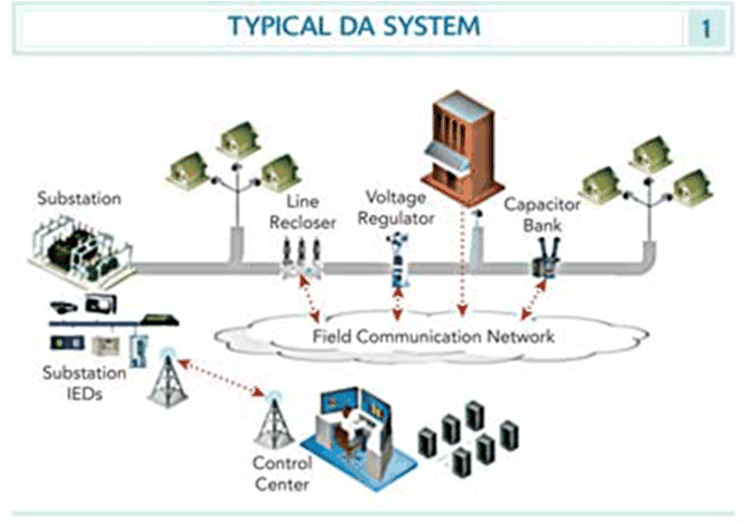
In North America, distribution systems are designed primarily with radial feeders that start in a substation and stretch out within a utility’s territory for short distances (< 1 mile) to long distances (50+ miles) (although many cities have secondary networks). Laterals connect from the feeder to reach customer sites. Most radial feeders also include one or two “normally open” switches between themselves and another feeder, usually fed from a different substation (if possible). The voltage ranges of feeders are typically between 2 kV and 34.5 kV (see Figure 6):
- Substation transformer that lowers the transmission voltage to the distribution voltage.
- Feeder breaker in the substation that protects the grid from feeder faults by tripping off.
- Load tap changer that tries to maintain a set feeder voltage and can raise or lower its transformer taps to modify the feeder voltage
- Recloser within or near the substation which is used to try to reclose 2 or 3 times after a momentary feeder fault to see if the fault clears by itself (e.g. a tree branch swinging in the wind)
- Feeder switches which are normally closed and which separate feeders into feeder segments. These switches are usually manually operated by field crews or may be remotely operated. Switches cannot operate on live feeders (breakers would be needed).
- Tie switch which is normally open and is used to “tie” between two radial feeders in case reconfiguration of the feeders is needed due to emergencies or maintenance activities.
- Voltage regulators along the feeder to boost voltage back up as it naturally declines over the length of a feeder. The rate of voltage drop is affected by the distance and by the amount and types of loads connected to the feeder.
- Capacitor banks judiciously placed along the feeder to compensate for vars (i.e. keep the power factor at its most efficient which is close to 1.0)
- Laterals (usually with protective fuses) which split off from the main feeder to reach to customer facilities
- Distribution transformers which connect a few customers (5 to 12 are typical numbers of customers per transformer) to the lateral, and transform the voltage down to the 120/240 V level for customer appliances.

Figure 6 : Basic structure of the Electric System (Developing a Business Case for Distribution Automation - Electric www.elp.com)