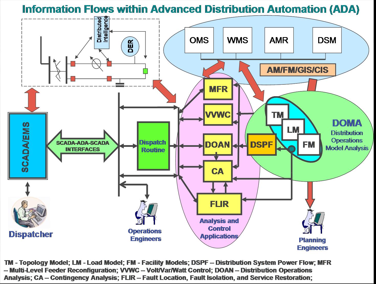
This application is based on a real-time
unbalanced distribution power flow for dynamically changing
distribution operating conditions. It analyzes the results of the
power flow simulations and provides the operator with the summary
of this analysis. It further provides other applications with
pseudo-measurements for each distribution system element from
within substations down to load centers in the secondaries. The
model is kept up-to-date by real-time updates of topology,
facilities parameters, load, and relevant components of the
transmission system.
The Distribution Operation Modeling and Analysis
supports three modes of operation:
1. Real-time mode, which reflects present conditions in the power
system.
2. Look-ahead mode, which reflects conditions expected in the
near future (from one hour to one week ahead)
3. Study mode, which provides the capability of performing the
“what if” studies.
The key sub-functions performed by the
application are as follows:
Modeling Transmission/Sub-Transmission System Immediately Adjacent
to Distribution Circuits
This sub-function provides topology and
electrical characteristics of those substation transformers and
transmission/sub-transmission portions of the system, where loading
and voltage levels significantly depend on the operating conditions of
the particular portion of the distribution system. The model also
includes substation transformers and transmission/sub-transmission
lines with load and voltage limits that should be respected by the
application.
Modeling Distribution Circuit Connectivity
This sub-function provides a topological model
of distribution circuits, starting from the distribution side of the
substation transformer and ending at the equivalent load center on the
secondary of each distribution transformer. A topological consistency
check is performed every time connectivity changes. The model input
comes from SCADA/EMS, Distribution SCADA, from field crews, from DISCO
operator, from AM/FM/GIS, WMS, and OMS databases, and engineers.
Data Management Issues between AM/FM/GIS and ADA Distribution
Connectivity Database
Standard interfaces between different AM/FM/GIS
databases, data converters, and ADA database are not developed yet for
practical use. The AM/FM/GIS databases were not designed for real-time
operational use. They lack many objects and attributes needed for ADA.
The population of the databases is not supported by an interactive
consistency check. The existing extractors of data and the converters
into ADA databases do not determine all data errors. The ADA
applications must conduct additional data consistency checking and
data corrections before recommendations and controls are issued.
Typically utility do not have established procedures for regular
update of the AM/FM/GIS databases by the operation and maintenance
personnel. Therefore many changes implemented in the field remain
unnoticed by the databases. Synchronization of the field state with
the ADA database is a challenge in modern utilities.
Data Management Issues
between CIS and AM/FM/GIS and ADA Distribution Connectivity Database
For the ADA applications, the AM/FM/GIS data
must be associated with the corresponding customer information data
from the CIS database. This data include billing data and description
of the customer specifics, such as rate schedule, customer code, meter
number, address, etc. The critical information is the billing data.
This data is updated based on metering cycles (typically one month)
and is not well synchronized. In order to synchronize billing data an
automated meter reading system should be implemented. In order to
update the ADA databases more frequently, which would increase the
resolution of ADA functions to individual distribution transformers
and even customers, a high capacity communication system should be
introduced to gather the data from hundreds of thousands of meters at
the same time. Some of the modern procedures enabled by AMR conflict
with the needs of ADA model.An example is the consolidated bills,
where the individual load data of distribution transformers located in
different sites of the consolidated company becomes unavailable for
the external to CIS world.
Modeling Distribution Nodal Loads
This sub-function provides characteristics of
real and reactive load connected to secondary side of distribution
transformer or to primary distribution circuit in case of primary
meter customers. These characteristics are sufficient to estimate kW
and kvars at a distribution node at any given time and day and include
the load shapes and load-to-voltage sensitivities (for real and
reactive power) of various load categories. In real-time mode, the
nodal loads are balanced with real-time measurements obtained from
corresponding primary circuits. A validity check is applied to
real-time measurements. The load model input comes from Distribution
SCADA, from CIS supported by AMR and linked with AM/FM/GIS, and
weather forecast systems.
Modeling Distribution Circuit Facilities
This sub-function models the following
distribution circuit facilities:
1.Overhead and underground line segments
2.Switching devices
3. Substation and distribution transformers, including step-down
transformers
4. Station and feeder capacitors and their controllers
5. Feeder series reactors
6. Voltage regulators (single- and three-phase) and their
controllers
7. LTC’s and their controllers
8. Distribution generators and synchronous motors
9.Load equivalents for higher frequency models
All facilities should be modeled with sufficient
details to support the required accuracy of Distribution Operation
Modeling and Analysis application.
Distribution Power Flow
The sub-function models the power flow including
the impact of automatically controlled devices (i.e., LTCs, capacitor
controllers, voltage regulators), and solves both radial and meshed
networks, including those with multiple supply busses (i.e. having
Distributed Energy Resources (DER) interconnected to the power
system).
Evaluation of Transfer Capacity
This sub-function estimates the available
bi-directional transfer capacity for each designated tie switch. The
determined transfer capacity is such that the loading of a tie switch
does not lead to any voltage or current violations along the
interconnected feeders.
Power Quality Analysis
This sub-function performs the power quality
analysis by:
1.
Comparing (actual) measured and calculated voltages against the limits
2.
Determining the portion of time the voltage or imbalance are outside
the limits
3.
Determining the amount of energy consumed during various voltage
deviations and imbalance
4.
Recording the time when voltage violations occur
5.
Performing modeling of higher harmonics propagation and resonant
conditions based on information available from the sources of harmonic
distortion
6.
Performing modeling of rapid voltage changes based on information
available from the sources of voltage distortion
The sub-function provides the ability to estimate
the expected voltage quality parameters during the planned changes in
connectivity and reactive power compensation.
Loss Analysis
This sub-function bases its analysis on technical
losses (e.g., conductor I2R losses, transformer load and
no-load losses, and dielectric losses) calculated for different
elements of the distribution system (e.g., per feeder or substation
transformer). For the defined area, these losses are accumulated for a
given time interval (month, quarter, year, etc.). They are further
compared with the difference between the energy input (based on
measurements) into the defined area and the total of relevant billed
kWh (obtained from the database), normalized to the same time
interval. The result of the comparison is an estimate of commercial
losses (e.g., metering errors and theft).
Fault Analysis
This sub-function calculates three-phase,
line-to-line-to-ground and line-to-ground fault currents for each
protection zone associated with feeder circuit breakers and field
reclosers. The minimum fault current is compared with protection
settings while the maximum fault current is compared with interrupting
ratings of breakers and reclosers. If the requirements are not met, a
message is generated for the operator.
Evaluation of Operating Conditions
This sub-function determines the difference
between the existing substation bus voltage and the substation bus
voltages limits.
The sub-function also estimates the available
dispatchable real and reactive load obtainable via volt/var control.
The operator or other applications can use this information for
selective load reduction. The sub-function provides aggregated
operational parameters for the transmission buses to be used in
transmission operation models.
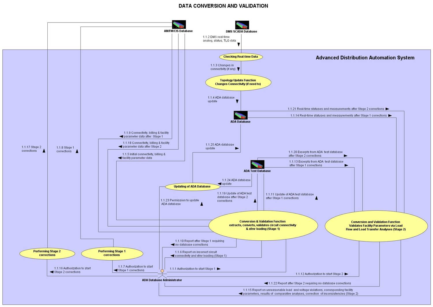
ADA
Database Administrator authorizes the
Conversion and Validation function to
extract, convert, and validate circuit
connectivity and distribution
transformer loading data. This is
referred to as Stage 1 validation.
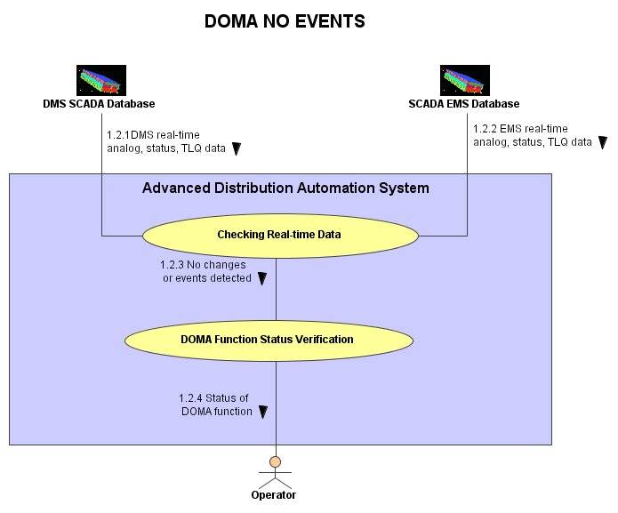
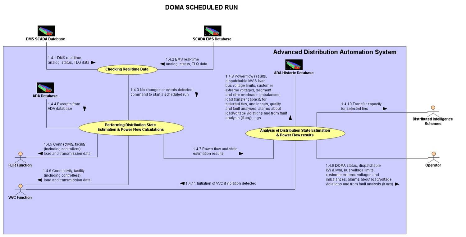
The data
in the latest download of DMS SCADA data
is checked by DOMA function for changes
in topology and used to obtain the
latest relevant analog data.
Issuing
report requiring no database corrections
after Stage 1
After
Conversion and Validation function
completes Stage 1 analysis it issues a
report showing that no further
corrections associated with
connectivity, billing or facility
parameter data are required.
Conversion and Validation function
ADA
Database Administrator
Report
showing that circuit connectivity and
transformer loading require no
corrections
Update
of ADA Test Database after Stage 1
corrections
After
Stage 1 corrections produce a report
with no connectivity and transformer
loading problems, the Conversion and
Validation function updates the ADA Test
Database which sets the stage for Stage
2 validation.
ADA
Database Administrator authorizes the
Conversion and Validation function to
validate facility parameters via load
flow and load transfer analyses. This is
referred to as Stage 2 validation.
Conversion and Validation function
receives excerpts from ADA Test Database
(after they were updated with Stage 1
corrections) to perform Stage 2
analyses.
ADA Test
Database
Conversion & Validation function
Excerpts
from ADA Test Database after Stage 1
corrections
Conversion and Validation function
receives latest statuses and
measurements from ADA Database (which in
turn are updated by DMS SCADA Database)
to perform Stage 2 analyses.
ADA
Database
Conversion & Validation function
Latest
statuses and measurements from ADA
Database
After
performing Stage 2 analyses, Conversion
and Validation function issues a report
for ADA Database Administrator.
Conversion & Validation function
ADA
Database Administrator
Report
on unreasonable load and voltage
violations, corresponding facility
parameters, results of comparative
analyses and correction of
inconsistencies
Conversion and Validation function
receives excerpts from ADA Test Database
(after they were updated with Stage 2
corrections) to perform the next round
of Stage 2 analyses.
ADA Test
Database
Conversion & Validation function
Excerpts
from ADA Test Database after Stage 2
corrections
Conversion and Validation function
receives latest statuses and
measurements from ADA Database (which in
turn are updated by DMS SCADA Database)
to perform the next round of Stage 2
analyses.
ADA
Database
Conversion & Validation function
Latest
statuses and measurements from ADA
Database
Issuing
report requiring no database corrections
after Stage 2
After
Conversion and Validation function
completes Stage 2 analysis it issues a
report showing that no further
corrections associated with unreasonable
load and voltage violations, or
corresponding facility parameters are
required.
Conversion & Validation function
ADA
Database Administrator
Report
showing that no further corrections
associated with unreasonable load and
voltage violations, or corresponding
facility parameters are required.
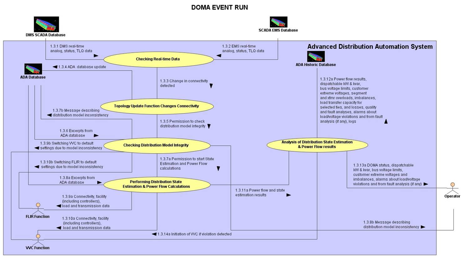
Topology Update function gives
permission to DOMA function to analyze
the distribution model integrity after
ADA database is updated with latest
changes.
Topology Update function
DOMA function
Permission to analyze distribution model
integrity
Upon completion of state estimation and
power flow calculations, DOMA function
makes the connectivity, facility
(including controllers), load and
transmission data available to FLIR
function.
DOMA function
FLIR function
Connectivity, facility (including
controllers), load and transmission data
Upon completion of state estimation and
power flow calculations, DOMA function
makes the connectivity, facility
(including controllers), load and
transmission data available to VVC
function.
DOMA function
VVC function
Connectivity, facility (including
controllers), load and transmission data
Analysis of
distribution state estimation and power
flow results
DOMA issues a report with results of
analysis of state estimation and power
flow calculations for storage in
historic ADA database.
DOMA function
Historic ADA database
Power flow results, dispatchable kW &
kvar, bus voltage limits, customer
extreme voltages, segment and xmfr
overloads, imbalances, load transfer
capacity for selected ties, losses,
quality and fault analyses, alarms (if
any) about load/voltage violations and
from fault analysis, logs
Analysis of
distribution state estimation and power
flow results
Selected results of analysis of state
estimation and power flow calculations
are made available for the operator,
EMS, and distributed intelligence
schemes.
DOMA function
Operator, EMS
DOMA function status, dispatchable kW &
kvar, bus voltage limits, aggregated
load characteristics, transfer capacity,
customer extreme voltages and
imbalances, alarms (if any) about
load/voltage violations and from fault
analysis
If checking the distribution model
integrity identifies a model
inconsistency, a message describing the
inconsistency is issued for storage in
ADA database.
DOMA function
ADA database
Message describing distribution model
inconsistency
Upon completion of state estimation and
power flow calculations, DOMA function
makes the connectivity, facility
(including controllers), load and
transmission data available to FLIR
function.
DOMA function
FLIR function
Connectivity, facility (including
controllers), load and transmission data
Upon completion of state estimation and
power flow calculations, DOMA function
makes the connectivity, facility
(including controllers), load and
transmission data available to VVC
function.
DOMA function
VVC function
Connectivity, facility (including
controllers), load and transmission data
Analysis of
distribution state estimation and power
flow results
DOMA issues a report with results of
analysis of state estimation and power
flow calculations for storage in
historic ADA database.
DOMA function
Historic ADA database
Power flow results, dispatchable kW &
kvar, bus voltage limits, customer
extreme voltages, segment and xmfr
overloads, imbalances, load transfer
capacity for selected ties, losses,
quality and fault analyses, alarms (if
any) about load/voltage violations and
from fault analysis, logs
Analysis of
distribution state estimation and power
flow results
Selected results of analysis of power
flow calculations are made available for
the operator and EMS.
DOMA function
Operator,
EMS
DOMA function status, dispatchable kW &
kvar, bus voltage limits, customer
extreme voltages and imbalances, alarms
(if any) about load/voltage violations
and from fault analysis
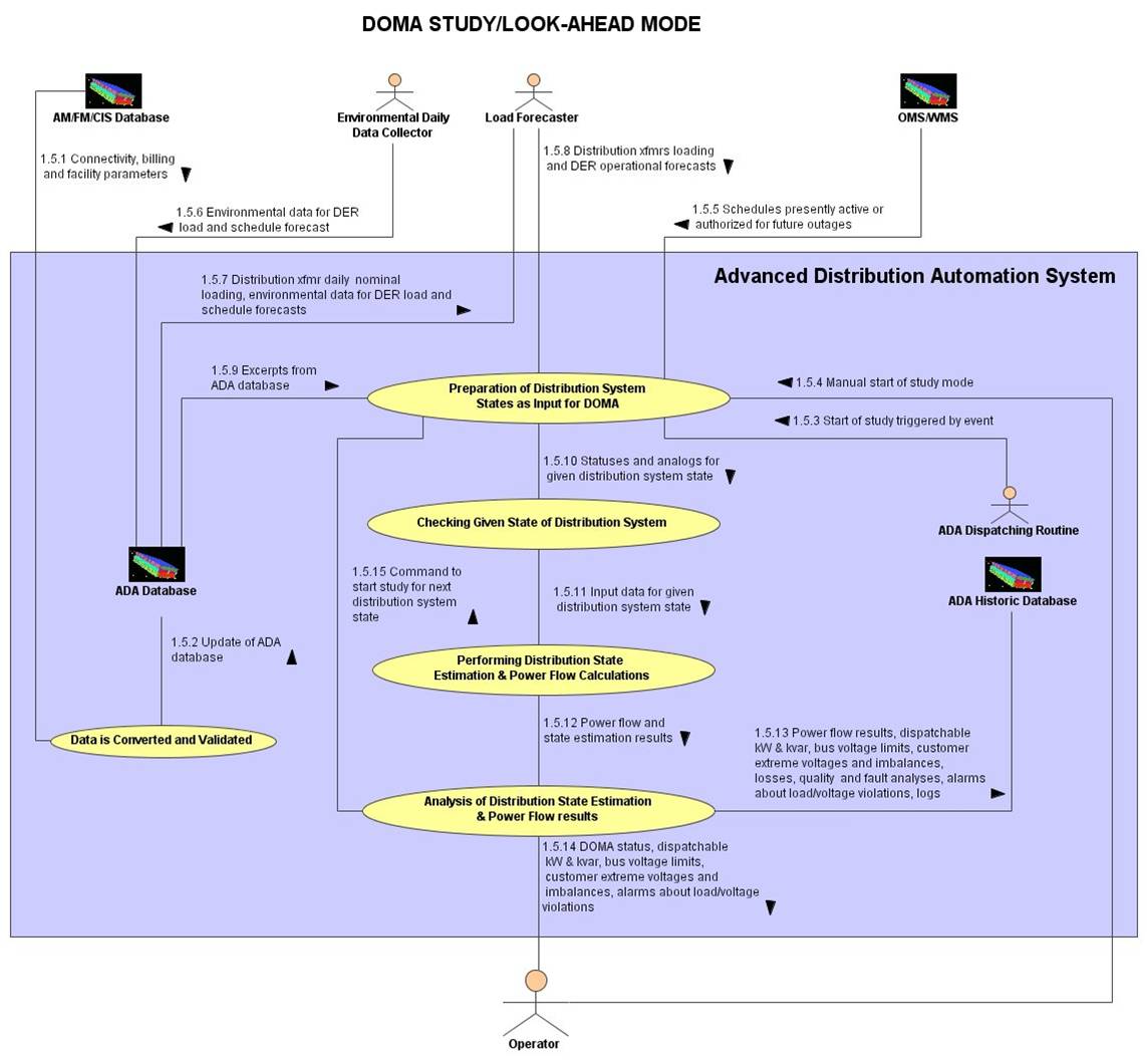
Conversion and validation function
receives the latest database download to
extract, convert and validate circuit
connectivity and transformer loading
data (Stage 1) as well as to validate
facility parameters via load flow and
load transfer analyses (Stage 2).
Preparation of
distribution system states as input for
DOMA
ADA dispatching routine, responsible,
among other things, for triggering
scheduled runs of various ADA functions,
issues a command to initiate the
look-ahead mode.
Preparation of
distribution system states as input for
DOMA
Load forecaster receives distribution
transformer daily loading data and
environmental data for DER load to be
used in preparation of distribution
system state.
ADA database
Load forecaster
Distribution transformers daily loading,
environmental data for DER load and
schedule forecasts
Preparation of
distribution system states as input for
DOMA
DOMA receives the distribution
transformer loading and DER operational
forecasts needed for preparation of
distribution system states to be studied
in the study and look-ahead modes.
Load forecaster
DOMA function
Distribution transformer loading and DER
operational forecasts
Analysis of
distribution power flow calculations
results
Analysis of the
results of the distribution power flow
calculations are made available for
archiving.
DOMA function
ADA historic database
Power flow results, dispatchable kW and
kvar, bus voltage limits, customer
extreme voltages and imbalances, losses,
quality and fault analyses, alarms about
load/voltage violations, logs.
Analysis of
distribution power flow calculations
results
Analysis of the
results of the distribution power flow
calculations are made available for the
operator.
DOMA function
Operator
DOMA status, dispatchable kW and kvar,
bus voltage limits, customer extreme
voltages and imbalances, alarms about
load/voltage violations.
User Interface
1.5.15
Preparation of
distribution system states as input for
DOMA
Upon completion of
analysis of the results of the
distribution power flow calculations
DOMA function issues a command to start
the study of the next distribution
system state.
DOMA function
DOMA function
Command to start the study of the next
distribution system state.