The
Integrated Energy and Communication Systems Architecture
Volume IV:
Technical Analysis
EPRI Project Manager
Joe Hughes
Cosponsor
Electricity
Innovation Institute Consortium for Electric Infrastructure to Support a
Digital Society (CEIDS)
EPRI • 3412
Hillview Avenue, Palo Alto, California 94304 • PO Box 10412, Palo Alto,
California 94303 • USA
800.313.3774 • 650.855.2121 • askepri@epri.com • www.epri.com
DISCLAIMER OF WARRANTIES AND LIMITATION OF LIABILITIES
THIS DOCUMENT WAS
PREPARED BY THE ORGANIZATION(S) NAMED BELOW AS AN ACCOUNT OF WORK SPONSORED OR COSPONSORED BY THE ELECTRIC
POWER RESEARCH INSTITUTE, INC. (EPRI). NEITHER EPRI, ANY MEMBER OF EPRI, ANY
COSPONSOR, THE ORGANIZATION(S) BELOW, NOR ANY PERSON ACTING ON BEHALF OF ANY OF THEM:
(A) MAKES ANY
WARRANTY OR REPRESENTATION WHATSOEVER, EXPRESS OR IMPLIED, (I) WITH RESPECT TO
THE USE OF ANY INFORMATION, APPARATUS, METHOD, PROCESS, OR SIMILAR ITEM
DISCLOSED IN THIS DOCUMENT, INCLUDING MERCHANTABILITY AND FITNESS FOR A PARTICULAR PURPOSE, OR (II)
THAT SUCH USE DOES NOT INFRINGE ON OR INTERFERE WITH PRIVATELY OWNED RIGHTS,
INCLUDING ANY PARTY'S INTELLECTUAL PROPERTY, OR (III) THAT THIS DOCUMENT IS SUITABLE TO ANY
PARTICULAR USER'S CIRCUMSTANCE; OR
(B) ASSUMES
RESPONSIBILITY FOR ANY DAMAGES OR OTHER LIABILITY WHATSOEVER (INCLUDING ANY
CONSEQUENTIAL DAMAGES, EVEN IF EPRI OR ANY EPRI REPRESENTATIVE HAS BEEN ADVISED OF THE POSSIBILITY OF SUCH
DAMAGES) RESULTING FROM YOUR SELECTION OR USE OF THIS DOCUMENT OR ANY
INFORMATION, APPARATUS, METHOD, PROCESS, OR SIMILAR ITEM DISCLOSED IN THIS
DOCUMENT.
ORGANIZATIONS THAT PREPARED THIS DOCUMENT
General Electric Company led by
GE Global Research (Prime Contractor)
Significant Contributions made by
EnerNex Corporation
Hypertek
Lucent Technologies (Partner)
Systems Integration Specialists Company, Inc.
Utility Consulting International (Partner)
ORDERING INFORMATION
Requests for
copies of this report should be directed to EPRI Orders and Conferences, 1355
Willow Way, Suite 278, Concord, CA 94520. Toll-free number: 800.313.3774, press 2, or internally x5379; voice: 925.609.9169; fax: 925.609.1310.
Electric
Power Research Institute and EPRI are registered service marks of the Electric
Power Research Institute, Inc. EPRI. ELECTRIFY THE WORLD is a service mark of
the Electric Power Research Institute, Inc. All other trademarks are the
property of their respective owners.
Copyright ©
2002, 2003, 2004 Electric Power Research Institute, Inc. All rights reserved.
CitationS
This document
describes research sponsored by EPRI and Electricity Innovation Institute.
The publication is a
corporate document that should be cited in the literature in the following
manner:
THE INTEGRATED
ENERGY AND COMMUNICATION SYSTEMS ARCHITECTURE, EPRI,
Palo Alto, CA and Electricity Innovation Institute, Palo Alto, CA: 2003
{Product ID Number}.
This is the technical analysis
volume. It is based on the architectural principles introduced in Volume I
section 3. Specifically it discusses in several concise sections and some large
appendices the details of the analysis and technical results produced by the
project.
To summarize, this
volume discusses:
|
·
Architectural Principles
|
Relates
the principles introduced in Volume I to the specifics of the analyses
detailing them herein
|
|
·
Architectural Analysis
|
The
high-level strategies used to solve the problem, the different environments,
as well as common services, information models, and interfaces that were
identified as the results of this analysis.
|
|
·
Technology Analysis
|
A
comparative analysis of the universe of technologies available and which are
most closely aligned with IntelliGrid Architecture requirements
|
|
·
Deployment Scenarios
|
To
identify common integration scenarios and detail how IntelliGrid Architecture can be used to
accomplish them.
|
|
·
Benefits and Conclusions
|
A brief
summary of the benefits from a technology and interoperability standpoint.
|
|
·
Appendices A..E
|
Detailed
discussions of research by the team
|
This section
reprises the levels of abstraction framework presented in Volume I. By successively
abstracting the architectural analysis via these descriptions, the dominant
aspects of architectural issues were exposed and detailed.
·
Business needs
·
Strategic vision
·
Tactical approach
·
Deployment scenarios
A primary goal of
IntelliGrid Architecture project is designing a common architecture for utilities. This
section summarizes the principle modeling/analysis elements identified and
applied in IntelliGrid Architecture
|
·
Requirements
|
Common
industry requirements permit application constraints to be concisely and
precisely defined.
|
|
·
Services
|
Refining
applications into the services that can be combined in various ways to
achieve functional goals.
|
|
·
Information models
|
Common
building blocks of information exchanged to accomplish applications.
|
|
·
Interfaces
|
Low
level primitives that act as atoms to build the molecular common services of
IntelliGrid Architecture. The definition of these atoms facilitates the conveyance of the common
services across environmental boundaries that may utilize different
technologies.
|
This section
summarizes the results of detailed analysis performed on the following
important but often considered independent subjects crucial to collectively
achieving a robust architecture.
·
Enterprise management
·
Data management
·
Platform
·
Communications
·
Security
In deploying
applications using IntelliGrid Architecture, this section identifies the issues to consider and
proposed solutions in performing integration.
|
·
Field Device Integration
|
Shows
how 61850 and DNP3 based SCADA systems can be integrated to provide unified
rich model based device access and control.
|
|
·
Enterprise Management
|
Encompasses
the integration of a DMTF based Enterprise Management systems with TC 57
based utility systems.
|
|
·
Application Integration
|
How a
deployment of the CIM and GID
can be used to create a platform for legacy application integration.
|
|
·
Data Analysis
|
As
recovery of money spent on asset related operations is not guaranteed, it is
critical that asset related costs be managed wisely.
|
|
·
Energy Market Integration
|
Describes
how a utility might integrate Energy Market Transaction Servers with utility
operational systems.
|
This section briefly
summarizes how IntelliGrid Architecture facilitates the realization of the following benefits:
·
Reusable infrastructure
·
Interoperability through standards
·
Available off the shelf adaptors
·
3rd party applications
·
Extensibility
·
Incremental approach
The following
table identifies and summarizes the major sections in this volume:
|
Section 1
Principles and Requirements
|
The overall
principles and requirements used to develop the architecture and a brief
description of the problems it was intended to solve.
|
|
Section 2
Analysis
|
The high-level
strategies used to solve the problem, the different environments, as well as
common services, information models, and interfaces that were identified as
the results of this analysis.
|
|
Section 3
Technology
Recommendations
|
Discussion of the
implementation of the common modeling elements (services, information models,
and interfaces) using specific recommended technologies within the defined
set of environments.
|
|
Section 4
Deployment Scenarios
|
Guidelines and
examples of how the architecture should be deployed by utilities.
|
|
Section 5
Benefits
|
Summarized the
benefits of IntelliGrid Architecture from a technical standpoint
|
|
Appendix A:
Security
|
A comprehensive
discussion of security considerations for energy industry and related
communications
|
|
Appendix B:
Network Management Technologies
|
A discussion of
network management technologies and needs
|
|
Appendix C:
Resilient Communication Services
|
Discusses those
technologies and requirements that are necessary for robust communications
networks.
|
|
Appendix D:
Technologies, Common Services, and Best Practices
|
A detailed summary
of all the individual technologies, common services, and best practices
identified by IntelliGrid Architecture project
|
|
Appendix E:
Environments
|
A detailed
description of IntelliGrid Architecture environments
|
Document Overview.. v
Architectural Principles v
Architectural Analysis v
Technology Analysis vi
Deployment scenarios vi
Benefits and conclusions vi
What is in this volume. vi
Contents. viii
List of Figures. xi
List of Tables. xiii
Architectural Principles
and Requirements. 1
Enterprise Activities and
Domain Use Cases 3
Strategic Vision. 5
Data Management and
Exchange Issues 5
Abstract Modeling Tools 6
Abstract Use Cases 10
Domain Use Case
Requirements Analysis 13
Analyses of Abstract Use
Cases 20
Abstract Use Case
Requirements Conclusion. 39
Tactical Approach. 41
Environments 42
Technology Independent
Architecture. 43
Technology Assessment 45
Architecture Conclusions 46
Deployment Scenarios 48
Enterprise Layering. 48
Migration. 50
Architectural Analysis. 1
Requirements Analysis 1
Aggregated Requirements 2
Domain Use Case Analysis 6
Abstract Use Case
Analysis 6
Common Services 33
Common System and Network
Management Services 34
Common Data Management
and Exchange Services 35
Common Platform Services 37
Common Security Services 38
Common Information Models 40
Enterprise Management
Common Information Models 41
Power Systems Common
Information Models 42
Generic Interfaces 44
Namespaces 48
IntelliGrid Architecture Environments 51
Conclusion. 52
Technology and
Implementation Recommendations. 1
Enterprise Management
Technologies 2
Analysis of Enterprise
Management Technologies 2
Overlapping/ Harmonizing/
Missing Enterprise Management Technologies 6
Data Management and
Exchange Technologies 7
Horizontal Data
Management Technologies 8
Field Device Technologies 12
Control Center/Operations
Technologies 21
Energy Market Energy
Market Technologies 44
Platform Technologies 47
Analysis of Platform
Technologies 47
Communications
Infrastructure Technologies 49
Analysis of
Communications Infrastructure Technologies 49
Communication
Infrastructure Integration and Federation Strategy. 56
Overlapping, Harmonizing
and Missing Communications Infrastructure Technologies 60
Security Technology
Overview.. 61
Interdependencies 61
Service Specific
Technological Recommendations 63
Communication Technology
Specific Recommendations 64
Technologies that need to
be created. 64
Deployment Scenarios. 1
Introduction. 1
Deployment Scenarios 2
Field Device Integration
Deployment Scenario. 2
Enterprise Management and
Power Systems Integration Deployment Scenario. 8
Application Integration
Deployment Scenario. 15
Asset Management
Deployment Scenario. 20
Energy Market Integration
Deployment Scenario. 25
Benefits. 1
Reusable Infrastructure. 1
Standards 1
Off the shelf Adapters 1
3rd Party Applications 1
Extensible. 2
Incremental approach. 2
Conclusion. 2
APPENDIX A - SECURITY....................................................................... A-1
APPENDIX B – NETWORK MANAGEMENT TECHNOLOGIES............... B-1
APPENDIX C – RESILIENT COMMUNICATION SERVICES..................... C-1
APPENDIX D – TECHNOLOGIES, SERVICES, AND BEST PRACTICES
................................................................................................................. D-1
Appendix E - Environments.............................................................. E-1
Figure 1‑1: IntelliGrid Architecture Framework. 2
Figure 1‑2 Domain
Use Cases From List of Business Functions. 5
Figure 1‑3:
Integrated Energy and Communication Systems Architecture (IntelliGrid Architecture) RM-ODP Model 8
Figure 1‑4 Abstract
Use Cases from Domain Use Cases. 11
Figure 1‑5
Environments from Requirements. 12
Figure 1‑6 The IntelliGrid Architecture
Abstract Use Cases. 12
Figure 1‑7 IntelliGrid Architecture
Secure Enterprise Architecture. 21
Figure 1‑8
Enterprise Management and Power System Management Treated Independently. 22
Figure 1‑9
Integration of Enterprise and Power System Management 23
Figure 1‑10 Energy
Market Transaction Service Communication. 27
Figure 1‑11
Integration Of Device Data. 30
Figure 1‑12
Applications To Be Integrated. 31
Figure 1‑13
Application Integration. 33
Figure 1‑14 Example
Of Integrated Data. 34
Figure 1‑15 Field
Service Integration Example. 35
Figure 1‑16:
Representation of Security Domain Concept 36
Figure 1‑17
Point-to-Point Integration. 40
Figure 1‑18 Diagram
of Components, Services, and Interfaces. 42
Figure 1‑19 Adapters
Use. 44
Figure 1‑20
Technology-Independent Architecture. 45
Figure 1‑21 IntelliGrid Architecture
Analysis Logic Flow.. 47
Figure 1‑22 Utility
Integration Layering. 49
Figure 2‑1 Example
of eCommerce Message Flow.. 9
Figure 2‑2 eCommerce
Registry. 10
Figure 2‑3 Exposing
Server Data. 14
Figure 2‑4 Device
Information Exchange Model 15
Figure 2‑5
Application Integration Example. 16
Figure 2‑6 Message
Queuing. 17
Figure 2‑7 Publish
and Subscribe. 17
Figure 2‑8
Traditional Data Warehouse Architecture. 21
Figure 2‑9 Common
Information Model Based Data Warehouse. 22
Figure 2‑10 Example
Of A Data Warehouse Star Schema. 23
Figure 2‑11 Data
Warehouse Connected to a Message Bus. 25
Figure 2‑12 Data
Mart Proliferation. 26
Figure 2‑13 Example
Of A CIM/GID Based Data Warehouse. 27
Figure 2‑14 Example
of CIM/GID Warehouse Connected to a Message Bus. 28
Figure 2‑15 Example
Information Model 43
Figure 2‑16 Use of a
Common Exchange Model 44
Figure 2‑17
Applications Connect to Off the Shelf Middleware Via the Standard API’s. 45
Figure 2‑18 Applying
Technologies to Environments. 46
Figure 2‑19 Ways
That A Generic Interface Can Be Applied. 47
Figure 2‑20 Example
Namespace. 49
Figure 2‑21 Example
Generic Interface. 50
Figure 2‑22 Summary
of IntelliGrid Architecture Environments. 52
Figure 2‑23
Technology Independent Architecture. 53
Figure 3‑1 RDF,
RDFS, and OWL Build on Existing W3C Work. 9
Figure 3‑2 The Tree
of Knowledge Technologies. 9
Figure 3‑3 RDF
Example. 10
Figure 3‑4 RDFS
Example. 10
Figure 3‑5 OWL
Example. 11
Figure 3‑6 The
Evolution of DNP3 and IEC61850. 13
Figure 3‑7 Profile
Comparison: Directed Communications – Connection-oriented. 15
Figure 3‑8 Profile
Comparison: Multi-cast communications – Connectionless. 16
Figure 3‑9 Service
Comparison. 17
Figure 3‑10 IEC61850
Object Model 19
Figure 3‑11 TC 57
Standards. 21
Figure 3‑12
Simplified Fragment of CIM Power System Model 23
Figure 3‑13
Simplified Fragment of CIM Asset/Work Model 24
Figure 3‑14
Generalizations for power system resource and conducting equipment 25
Figure 3‑15 Defining connectivity for conducting
equipment 26
Figure 3‑16
Transformer model illustrating use of aggregation. 27
Figure 3‑17:
IEC61850 Models and Connections with IEC61970 Models. 28
Figure 3‑18 Proposed
Harmonization of 61850 and 61970 Information Models. 31
Figure 3‑19 Example
of a Full Mesh type of Namespace. 35
Figure 3‑20 Example
TC57PhysicalNamespace. 36
Figure 3‑21 Example
TC57ClassNamespace. 36
Figure 3‑22 Example
TC57ISNamespace. 37
Figure 3‑23
Traditional view of utility data. 37
Figure 3‑24 Customer
data within a CIM Network View.. 38
Figure 3‑25 Example
Full Mesh Namespace. 39
Figure 3‑26
Interface Lineage. 40
Figure 3‑27 Example
Of The Use Of The High Speed Data Access Interface. 41
Figure 3‑28 Example
Of The Use Of The Time Series Data Access Interface. 42
Figure 3‑29 CIM/GID
Based Data Warehouse. 42
Figure 3‑30
TC57Namespace Used As A Subscription Topic Tree. 43
Figure 3‑31 Model
Driven Message Definition. 44
Figure 3‑32 Migration To 61850 In The Substation
Communications Environment 58
Figure 3‑33 Next Generation SONET --- the
Multi-service Approach and its Benefits. 60
Figure 4‑1 Proposed
Harmonized IEC61850 and IEC61970 Information Models. 4
Figure 4‑2 DNP and
IEC61850 Based SCADA Networks. 4
Figure 4‑3 Mapping a
Device Model to the CIM.. 6
Figure 4‑4 Wrapping
DNP with a IEC61850 Based Namespace. 7
Figure 4‑5 Today's
Enterprise Management Architecture. 8
Figure 4‑6 A
Web-based Interface to the Enterprise Management System.. 9
Figure 4‑7 Web-based Enterprise Management Architecture,
which enables the Integration and Federation of Heterogeneous IntelliGrid Architecture management
technologies. 11
Figure 4‑8
Collaborations amongst multiple Management Systems. 11
Figure 4‑9 The
Internal Architecture of a WBEM Server and its interactions with Management
Application Clients and Managed Devices/Systems. 12
Figure 4‑10 Using A
Separate DMTF Integration Layer 14
Figure 4‑11 Using
DMTF CIM Only On The Enterprise Integration Layer 15
Figure 4‑12 More
Complete Integration. 15
Figure 4‑13
Application Integration Scenario. 15
Figure 4‑14 Control
Center Application Integration. 17
Figure 4‑15 Specific
GID Interfaces Used For Application Integration. 17
Figure 4‑16 Data
Synchronization. 18
Figure 4‑17 Keeping
the Mapping From Assets To the Power System In Sync. 19
Figure 4‑18 CIM/GID
Based Data Warehouse With Message Bus. 21
Figure 4‑19 Asset
Management Integration Example. 22
Figure 4‑20 Combined
Application Integration And Data Integration Architecture. 23
Figure 4‑21 GID
Interfaces Used to Integrate Applications and Data. 24
Figure 4‑22 ETSO
ebXML Or NERC eTagging Based Energy Market Server 26
Figure 4‑23 CME
Based Integrated Energy Market Systems. 27
Figure 4‑24 ETSO or
eTagging Based Integrated Energy Market Systems. 27
Table 1‑1 Principles
Applied to Each Level of Abstraction. 2
Table 1‑2 Summary of
RM-ODP Viewpoints. 7
Table 1‑3 Enterprise
Levels. 48
Table 2‑1: Relating
Security Processes to Functions and Services. 29
Table 2‑2: Relating
Security Processes to Functions and Services. 30
Table 2‑3: Primary
Services and the additional Security Services required to implement 30
Table 2‑4: Services
needed for Intra/Inter Domain Security. 32
Table 3‑1 Matrix Of
GID Functionality. 32
Table 3‑2: A
comparison of various Wireless Data Technologies. 55
Table 3‑3: Security
Services vs. Security Domain Usage. 62
Table 3‑4: Summary
of recommendations for Identity Establishment and Confidentiality. 64
This
page intentionally left blank.
If one were to
envision a utility where an IntelliGrid Architecture based architecture had been completely
adopted, one would see that it provides an ideal platform for higher-level
analysis across the entire enterprise. A
simple analogy might be that a utility executive ideally wants to drive a
utility much like a pilot might fly an airplane during cloudy conditions. In this case, a pilot can use just
instruments to get a complete picture.
That is, all required aspects of fight operation are visible via a well
laid out set of instruments. Similarly,
since most utility operational information and risk is not visible unaided, a
utility manager uses a set of software components as instruments to get a
complete picture. The instruments condense and summarize all the required
information. To actually direct the airplane, the pilot uses a mechanical
interface consisting of a limited set of pedals, switches, levers, and
“steering wheel”. How the instruments
and mechanical interface connect to the airplane and outside world is in
someway irrelevant to the pilot. One
could say that pilots only care that a set of inputs lead to a set of desired
results via comprehensive user interface.
Similarly, a utility executive wants a simple set of applications to
help direct the utility enterprise.
It is this unified comprehensible user
interface that IntelliGrid Architecture ultimately seeks to enable. This interface may exist at many levels of
the utility. For example, an executive
may be primarily concerned with balancing profit and risk whereas an
operational supervisor may be primarily concerned with balancing income and
reliability. However, it is clear that
the primary goals of IntelliGrid Architecture are to enable a comprehensive view of operations and
analytics in a secure manner.
These end-to-end analysis applications largely
don’t exist today because without a single unifying architecture they are too
expensive to develop. There are a great
variety of systems being used in a utility. In order to get a true picture of
the entire utility, these systems and data need to be integrated. Consequently, development of the end to end
analysis application can be hugely expensive.
Therefore in the past, even though the integration was technologically
feasible, it was not practical because the expense was prohibitive. It is IntelliGrid Architecture Team’s belief that only via
the deployment of a unified architecture and standard solutions can the new
analysis applications be economically deployed.
The IntelliGrid Architecture provides a unified architecture to realize this vision.
This
section starts with the requirements of utility industry applications that are
captured in the form of Domain Use Case. However, focusing on the applications
alone often bypasses the creation of common infrastructure capabilities that,
while burdensome to create for a single application, make it possible to
realize the myriad of functions that utility participants anticipate. In order
to focus on the capabilities of the shared architecture upon which secure
end-to-end looking applications can be built, we examine six essential
“abstract use cases” that describe the requirements of the common
architecture. This section shows the
derivation of these Abstract Use Cases and then describes the analysis done by
IntelliGrid Architecture team to develop the architecture.
As the analytical
phases of IntelliGrid Architecture project progressed, the team iteratively analyzed use cases
and derived solutions at subsequent levels of abstraction with increasing
detail. A useful analogy is to say that
the analysis began by starting from business needs, and gradually descending
towards a more nearly realizable solution via design goals, abstract design and
technology recommendations. We reprise
this analogy from Volume I section 3 in Figure
1.
Figure
1: IntelliGrid Architecture Framework
This figure shows the levels of abstraction
used during IntelliGrid Architecture Enterprise Architectural Analysis.
At each level of
abstraction, the team looked to discover commonality so that a unifying
architecture could be discovered. The
levels are described in Table
1.
|
Table 1 Principles Applied to Each Level of Abstraction
|
|
Level of
Abstraction
|
Principles
applied to each problem area at this level
|
|
Business Need
|
The Business
Needs of the power industry were identified and their information
requirements were assessed in the analysis of the utility operations
functions and management.
|
|
Strategic
Vision
|
The Strategic
Vision for the IntelliGrid Architecture reflects the ultimate objectives
for an information infrastructure that can meet all of the business needs,
including network configuration requirements, quality of service
requirements, security requirements, and data management and exchange requirements. This Strategic Vision is based on unifying:
–
Abstract Modeling
–
Security Management
–
Network and System Management
–
Data Management and Exchange
–
Integration and Interoperability
|
|
Tactical
Approach
|
The Tactical Approach uses Information
Models, Common Services and Generic Interfaces to provide a deployment
environment and technology independent solution for implementing
interoperable systems and for managing the migration from legacy systems
toward fully integrated systems.
|
|
Technology and
Best Practices
|
This section
describes how the Tactical Approach may be realized using implementable
technologies. It compares recommended
technologies and discusses their merits in regard to how well they support
the IntelliGrid Architecture.
|
|
Deployment
Guidelines
|
Provides
guidelines on how to apply the architecture in a layered manner. This is intended to help system designers
create migration plans in which legacy applications can be adapted to conform
to the architecture and new applications can be non-disruptively added.
|
The remainder of
this section discusses the principles applied at each level of abstraction in
more detail.
IntelliGrid Architecture is designed
to provide an architecture to be used across all of the utility. The first task that IntelliGrid Architecture Team undertook
was the creation of a comprehensive list of over 400 Enterprise
Activities. Simultaneously with the
development of this list, some common themes quickly became apparent as the
project team analyzed the requirements.
It was clear that the architecture would need to provide common
strategies in the following areas that underlay nearly all of the requirements
that were gathered:
·
Network and System (Enterprise) Management. For an area that is relatively mature in
commercial networks, the science of monitoring and controlling the
communications network itself is surprisingly unknown or at the very least,
primitive, in power system automation.
The key here will be to harmonize network monitoring technologies and
network object models with the functional equivalents in the power industry,
and to integrate both with security management.
·
Data Management and exchange. The sheer volume and variety of data required
in order to operate a power system within the Digital Society poses staggering
challenges in standardizing interfaces for reading, writing, publishing, and
subscribing to data. In this area, the
key solution will be to identify specific commonality and diversity of how data
is managed and exchanged.
·
Basic networking and connectivity
infrastructure. How are the myriads of
device and communications technologies to connect? In general, IP-based networks were the
obvious solution, but utility requirements posed unique requirements of
reliability, wireless access, changing configurations, and quality of service.
·
Security and access control. Deregulation and other effects of the Digital
Society are forcing utilities to rely on public networks provided by third
parties, communicate with their competitors, cross organizational boundaries,
and expand their communications networks inward to their own organizations and
outward to the customer. All of these
forces make the need for cyber-security ubiquitous in power system operations. Encryption and authentication technologies
abound, but the chosen strategy is to tailor security solutions to particular
problem domains, and link them together with shared security management
services.
The Team used the
list of requirements to select a set of functions from the list of Enterprise
Activities on the basis of their architectural significance -- that is the architectural sophistication
necessary to achieve their implementation.
Called Domain Use Cases, this small set of functions more intensively
analyzed consist of:
·
Wide Area Measurement and Control – in
particular, the requirements for developing a self-healing, self-optimizing
grid that could predict emergencies rather than just react to them, and
automate many reliability functions currently done manually or not at all.
·
Advanced Distribution Automation –the
challenges raised by the use of Distributed Energy Resources, renewable energy
sources, and the use of fault detection, fault location, sectionalization and
automatic service restoration over wide areas of the service territory and
multiple organizational boundaries.
· Customer
Interface – including the challenges of real-time pricing, demand response,
automatic metering, integration of the utility communications network with
building automation, and the requirements needed to integrate real-time data
gathered from the power network with business policies in order to securely
enable trading of energy in a deregulated environment.
This process
illustrated in Figure 2:
Figure
2 Domain Use Cases From List of Business Functions
The amount of data
being collected or capable of being collected is increasing exponentially. This
rapid expansion of data retrieval results from the fact that more field devices
are being installed and that these field devices are becoming more
"intelligent" both in what power system characteristics they can
capture, and also in what calculations and algorithms they can execute which
result in even more data.
As distribution
automation extends communications to devices on feeders, as substation
automation expands the information available for retrieval by substation
planners, protection engineers and maintenance personnel, and as more power
system asset information is stored electronically in Geographical Information
Systems and AM/FM systems, even more varieties and volumes of data will need to
be maintained and managed.
Data management is
a complex issue, encompassing many aspects of data accuracy, acquisition and
entry, storage and access, consistency across systems, maintenance, backup and
logging, and security. These are discussed in the following sections.
Data management
must address a complex set of issues that include the following services:
·
Validation of source data and data exchanges
·
Ensuring data is up-to-date
·
Management of time-sensitive data flows and
timely access to data by multiple different users
·
Management of data consistency and
synchronization across systems
·
Management of data formats in data exchanges
·
Management of transaction integrity (backup and
rollback capability)
·
Management of the naming of data items
(namespace allocation and naming rules)
·
Data Accuracy
·
Data Acquisition
·
Data Entry
·
Data Storage and Access Management
·
Data Consistency across Multiple Systems
·
Database Maintenance Management
·
Data Backup and Logging
No single
cross-industry technology addresses all of these issues, but multiple solutions
and best practices are available for different aspects.
The first
principle of IntelliGrid Architecture architectural vision is the principle of abstract
modeling techniques, as expressed in the following quote:
“There are limits to human ability to
understand [truly complex systems] and to solve large sets of system
equations. The problem must be broken
down or divided into a series of smaller problems that can be solved. Modeling is one of the proven and
well-accepted engineering techniques that simplify the system, so that we can
better understand the system being developed.
System simplification is achieved through the introduction of levels of
abstraction, which allow the modeler to focus on one particular aspect of the
system at a time.”
So that the
abstractions used in IntelliGrid Architecture analysis may be more clearly understood, the
IntelliGrid Architecture has been developed and refined using an international
standard for architecture design call the “Reference Model for Open Distributed
Processing” framework, RM-ODP. RM-ODP is the reference model for defining open,
distributed software system architectures. It was developed with extensive
input from the technical community and represents a substantial body of
knowledge. It was therefore the natural selection as a means for developing and
expressing IntelliGrid Architecture.
RM-ODP is a formalized approach to developing
abstract models of system functions, which helps to ensure that all
requirements are identified and analyzed before the functions are
implemented. It breaks down the analysis
and description of an architecture into five largely complimentary
viewpoints. Each viewpoint answers a
different set of questions. These
viewpoints are summarized in the following table.
|
Table 2 Summary of RM-ODP
Viewpoints
|
|
Viewpoint
|
Question
|
Contains
|
|
Enterprise
Viewpoint
|
Who is
involved?
|
Information
about the various participants and functions implemented in the energy
industry
|
|
Information
Viewpoint
|
What
information must be exchanged?
|
Models of
information exchanged, agreements between parties, and roles and
relationships that underpin the data of industry functions
|
|
Computational
Viewpoint
|
How is this
information going to be exchanged?
|
The mechanics
related to information exchange i.e. a discussion of the interfaces required.
|
|
Engineering
Viewpoint
|
Where is the
information located and where will it be sent?
|
The
configuration for where to physically deploy clients, servers, databases, and
subsystems in terms of what component is deployed on which network for
example. This view describes the
partitioning of a solution and where the pieces reside and closely
corresponds to IntelliGrid Architecture Environments.
|
|
Technology
Viewpoint
|
Which
technologies and best practices are to be used to accomplish this?
|
Actual
technology and best practice solutions that can be used to carry out the
functions
|
It is important to note
that RM-ODP is a framework for describing architectural
views, and provides a reference model for developing architectures, but it is
not an architecture itself.
In the IntelliGrid Project, the main purpose for using RM-ODP was to ensure that all architecturally
significant requirements were identified for existing and future power
system operations functions.
The Unified Modeling
Language, UML, provided both the abstract language and computer tools that the
team employed for expressing its analysis within the RM-ODP framework. These two approaches, RM-ODP and UML, complemented each other in the
development of the architecture:
·
As a framework, RM-ODP is very abstract and does not call out the
use of a particular notation nor does it have tools that are directly linked to
its concepts.
·
UML has very good tools available, but is not an
architecture standard and is not usually used at the same level of scope as RM-ODP.
The two can be used
together because they are complementary and support similar levels of
abstraction. Even though there is not a direct match between RM-ODP terms and UML terms, constructs can be
developed in UML to realize RM-ODP
concepts. The widely available UML tools
can then be used to create the diagrams and underlying database that is
necessary for understanding the complex interactions of power system functions
across multiple areas. Both are useful
standards as both embody the following concepts:
·
UML is a technology neutral way of specifying use
cases, data, and software components.
RM-ODP separates technology specifics into the
Technology View. IntelliGrid Architecture uses UML to
specify a technology neutral architecture.
·
UML is a deployment neutral way of specifying
data and software components. RM-ODP separates deployment specifics into the
Engineering View. IntelliGrid Architecture uses UML to
specify deployment neutral architecture that can be applied to a variety of
environments.
In conclusion, UML and
RM-ODP have enabled IntelliGrid Architecture Team to design an
architecture that is flexible and can be applied to a diverse set of
environments and technologies. UML and
RM-ODP provide a standard language so that the
design of the architecture can be communicated to others.
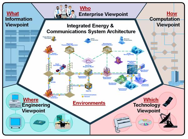
Figure
3: Integrated Energy and Communication
Systems Architecture (IntelliGrid Architecture) RM-ODP Model
The abstract
modeling process used during IntelliGrid Architecture project leading from RM-ODP to the final architecture is outlined below.
In general, the UML concept of “Use Cases” was used to capture stakeholder
requirements, and a UML tool called Magic Draw was used to generate diagrams
that expressed the architecture in the five RM-ODP viewpoints.
1.
UML Use Case
Template: The highest level UML construct for describing a function is the
Use Case, which can map more or less into the RM-ODP Enterprise Viewpoint. Since not many people
have UML tools, people in the IEC and IEEE have been describing functions using
a “Use Case Template”. A Use Case
Template is a MS Word document that captures the UML concepts of Actors, Roles,
Associations, Classes, and other UML constructs. This Use Case Template could
then be used to enter the information into a UML tool, like Rational Rose or
Magic Draw. The Use Case Template doesn’t have any standard format, but usually
includes sections to:
·
Describe the function in narrative form
·
Identify the Actors and Information Exchanged
·
Identify the steps involved in exchanging
information between Actors.
2.
UML Use Case
Template to IntelliGrid Architecture Domain Template: In IntelliGrid Architecture project, the team renamed
the Use Case Template the “Domain Template” and modified it in a number of
ways:
·
Added a number of additional fields and
requirements beyond those of a traditional UML Use Case in order to capture
more RM-ODP concepts, such as policies and contracts
between Actors.
·
Added the RM-ODP concept of Common Services (services that
can be used by many different functions) as well as a spreadsheet to capture
common requirements across all Use Cases.
·
The IntelliGrid Architecture team identified a number of common
Environments, discussed later in section 2.
Each environment has different configuration, performance, security and
data management requirements. Each
“step” in a Use Case was assigned to a particular environment for use later in
determining appropriate technologies to use for that step.
3.
Importing Domain
Templates into UML Tool: Domain
Experts filled out Domain Use Cases using the Domain Template. These were then
imported automatically into the Magic Draw UML tool. The resulting diagrams
became a tool for IntelliGrid Architecture team to further analyse the requirements captured
in the Domain Templates.
4.
Results from the
RM-ODP
Analysis Become the Technology and Deployment Neutral Reference Architecture:
As stated above, RM-ODP is a reference model for defining a distributed
system architecture for a particular software function. However, the purpose of
IntelliGrid Architecture project is not to develop a single architecture for one specific
function; the purpose of IntelliGrid Architecture project is to develop a Reference Architecture
for all
power system functions. The
relationships captured in the UML tool can be used as a database for
determining the appropriate approach to any power system communications
problem. In this sense, the database
becomes the architecture.
Through analysis
of the Domain Use Cases, the team identifies a limited set of common functions
necessary to implement each Domain Use Case. In order to capture this common
functionality IntelliGrid Architecture team derived a set of Abstract Use Cases. The Abstract Use Cases are:
·
Integration of Enterprise Management – The
integration of software and hardware component management functions with power
system functions
·
Integration of Utility Wholesale and Retail
Market Operations - The integration of market operation functions with power
system functions
·
Device Integration – The integration of
heterogeneous power system devices.
·
Application Integration – The integration of
heterogeneous power system applications to meet operational needs.
·
Data Integration – The integration of
heterogeneous power system data to meet analytic needs.
·
Security Integration – The integration of
security across multiple domains.
The process of
using Domain Use Cases to derive Abstract Use Cases is a key simplification
used by IntelliGrid Architecture Team. That is, the
Team realized that it would be impossible to analyze all conceivable Domain Use
Cases within a limited timeframe and budget.
Instead, the Team realized that they had to pick a much smaller set of
“architecturally significant” Domain Use Cases. These “architecturally significant” use
cases were then used to create more generalized Abstract Use Cases as
illustrated in Figure 0‑4.

Figure
0‑4 Abstract
Use Cases from Domain Use Cases
This second set of
use cases is abstract because they are not tied to any particular utility
function. However, the Abstract Use
Cases are more useful in deriving detailed components of an architecture
because they allowed the Team to abstract away the specifics of Domain Use
Cases and permitted the team to focus on the commonality and diversity of all
Domain Use Cases. The commonality is
expressed as a set of common modeling elements and the diversity is expressed as
a set of environments and technologies as shown in Figure 5:
Figure
5 Environments from Requirements
The abstract set
of use cases is illustrated in Figure6 below:
Figure6 The IntelliGrid Architecture Abstract Use Cases
This section
discusses the derivation of the Abstract Use Cases from the Domain Use Cases.
ADA
Advanced
Distribution Automation (ADA) involves software applications in the control
center supplemented by applications and functions implemented in field
equipment. The control center applications provide the global analysis of the
distribution system state and capabilities and are the overarching functions in
control of distribution system operations, while the field equipment
applications provide local information and control.
The ADA
applications in the control center rely heavily on data from many different
sources, and going to different systems:
·
SCADA system for real-time data from field
equipment and control command to field equipment, including both substations
and feeder equipment
·
DER
equipment, either directly or indirectly through DER Aggregators
·
Energy Management System (EMS) for transmission information and
·
Geographical Information System (GIS) and/or Automated Mapping and Facilities
Mapping (AM/FM) systems for power system facilities data and physical
connectivity data
·
Customer Information System (CIS)
·
Work Management System (WMS)
·
Distribution Planning Systems
·
Market Operations systems
The primary
architectural requirements for ADA are focused on data management. Correct,
available, and timely data are crucial to the ADA function operating properly.
However, since data comes from many different sources and since the systems
acting as these sources usually are provided by different vendors, the
coordination, synchronization, integration of systems, and mapping of data
elements across these systems is a major problem.
In addition,
because real-time control of the power system is a major aspect of ADA, both
security and network management are critical to safe and reliable operation of
the power system. Therefore the main requirements are those associated with the
“Critical Operations DAC” Environment and the “Intra-Control Center”
Environment ( a complete list of IntelliGrid Architecture Environments can be found in Appendix
E):
1.
Security Requirements
·
Provide Authorization Service for Access Control
(resolving a policy-based access control decision to ensure authorized entities
have appropriate access rights and authorized access is not denied)
·
Provide Information Integrity Service (data has
not been subject to unauthorized changes or these unauthorized changes are detected)
·
Provide Audit Service (responsible for producing
records, which track security relevant events)
·
Provide Credential Renewal Service (notify users
prior to expiration of their credentials)
·
Provide Security Policy Service (concerned with
the management of security policies)
·
Provide Single Sign-On Service (relieve an
entity having successfully completed the act of authentication once from the
need to participate in re-authentications upon subsequent accesses to managed
resources for some reasonable period of time)
·
Provide User Profile and User Management
(combination of several other security services)
·
Provide Security Discovery (the ability to
determine what security services are available for use)
2.
Network and System Management Requirements
·
Provide Network Management (management of media,
transport, and communication nodes)
·
Provide System Management (management of end
devices and applications)
3.
Data Management Requirements
·
Support the management of large volumes of data
flows
·
Support keeping the data up-to-date
·
Support extensive data validation procedures
·
Support keeping data consistent and synchronized
across systems and/or databases
·
Support timely access to data by multiple
different users
·
Support frequent changes in types of data
exchanged
·
Support management of data whose types can vary
significantly in different implementations
·
Support specific standardized or de facto object
models of data
·
Support the exchange of unstructured or
special-format data (e.g. text, documents, oscillographic data)
·
Provide discovery service (discovering available
services and their characteristics)
·
Provide conversion and protocol mapping
Therefore, if one
abstracts from these functions, one can say that ADA from an architectural
perspective requires:
·
Integration of many different systems developed
by different vendors for differing requirements
·
Development of a platform that spans many
different systems, applications, and databases
·
Management of data across multiple systems,
including data consistency and synchronization with short timeframes
·
A system to manage configuration and change
·
Security integration across multiple security
domain
Customer Interface
With the advent of
deregulation, the interface between ESP and consumer has become more important,
because customers can (and have) switch(ed) energy providers and because they
can now be an additional source of revenue if new energy services can be sold
to them, or if the utility rights within the customer premises can be used to
sell access to other businesses.
The expansion of
system operations coordination and control down to the end user level creates
one of the key justifications for IntelliGrid Architecture. An enterprise-wide architecture such
as IntelliGrid Architecture offers a tremendous opportunity for improved operational efficiency,
improved control of customer processes based on supply system conditions, use
of customer-owned and operated generation and power quality improvement
technologies as part of overall system management and to achieve the required
levels of reliability and power quality at the end user level. In as far as the other side of the equation,
implementation of load control/demand response programs provides utilities with
another key tool to ensure power system stability and security.
Applications
related to customer interface must be coordinated closely with distribution
automation and distributed resource applications, as well as market
operations. Key applications include
·
Real time pricing
·
Load management
·
Residential customer applications, such as load
control in response to real time pricing incentives
·
Direct customer energy management and load
control during system emergencies
·
Automatic evaluation of and recommendations for
increasing energy efficiency based on profiles of the customer site and loads
·
Control and performance evaluations for
residential generation
·
Power quality assessments and control.
Also critical are
commercial and industrial (C&I) applications such as commercial customer
participation in energy markets through aggregation of backup generation and
energy management, participation in ancillary services (such as volt/var
control, harmonic control, and reserve generation), real time commercial
facility power quality assessment solutions integrated with the distribution
system operation and integration of real time information concerning system
power quality and reliability.
By nature,
customer interface/consumer services applications share close coordination with
distributed automation, distributed resource, and market operation
applications. The current status of
utility industry restructuring, as well as the current state of technology,
necessitate that many consumer service applications rely on distributed
automation and distributed energy applications and their underlying
communications requirements.
Furthermore, consumer interface is playing a key role in market
operations where customer load and/or onsite generation may be aggregated and
utilized to bid into energy markets and key customers may have sufficient
requirements for power to play a role in bulk power trading, scheduling, and
supply scenarios.
The range and
scope of customer interface/consumer service applications is complex and
growing. The possibility of customers
and ESPs managing load down to the appliance level could generate requirements
with a level of granularity not seen in any other domain. However, at the present time and taking both
short and long term scenarios into consideration, the domain analysis covered
three key applications:
·
Real time pricing
·
Utility administered load control
·
Consumer side data collection
RTP is important because it requires
communication between the customer and the ESP in terms of the ESP providing RTP signals to the customer and the customer
potentially providing bids and forecasts back to the ESP.
Quality of service including high availability and timeliness of data is
crucial. There are large numbers of
customer with sensitive information on pricing and usage; therefore security is
a key consideration. Since future power
system operating scenarios will undoubtedly involve more two-way communication
with the customer and the ESP
as well as increased customer sensitivity to pricing data, this is a
significant area for requirements analysis.
Utility
administered load control is where, instead of responding to price signals, the
signal comes directly from the ESP
to control customer loads. This
application covers a wide range of issues, especially security across
organizational domains and the need for two-way communications to confirm load
control actions for future advanced demand responsive systems.
Data collection
from the consumer side is seen as critical to facilitate more active
involvement by customers in the interface to and participation in market
operations and energy management. In
terms of power quality monitoring, the information is intermittent and
sometimes infrequent, but timely, communication and notification is very
important when events do occur.
Analysis of the
requirements associated with these requirements showed trends that were common:
·
Database integration and management is critical,
with utilization on both customer and ESP systems and even inside one system, with
multiple installations and different purposes.
For instance, for ESPs, there may be one database for customer billing
data, a database for pricing data, and a separate database for operational
data, i.e., customer participation in RTP or load control programs. Some of the data requirements are low in
volume (such as usage data) while others may be high in volume with detailed
information (such as power quality monitoring data).
·
There are multiple levels and requirements of
security and in addition to ESP
security issues, which are significant and substantial, there are issues
relating to the privacy of customers and desire to secure customer data and
facilities from unauthorized access and cyber attack. Securing the consumer interface frequently
requires different technologies than securing ESP-specific functions.
·
Communication and bandwidth requirement run the
gamut from telephone line to wireless to fiber.
Much equipment related to customer metering has not been upgraded to
take advantage of the state of the art, so legacy systems and disparate data
transportation mechanisms require an enterprise-level approach to systems
integration.
·
Customer services factor in financial
transactions. Much as with market
operations, money will be changing hands in applications such as power trading
and real time pricing. This brings into
play a different set of considerations than the traditional ESP operations.
·
The amount, scope, and time frame for
transactions are constantly evolving. As
more customer services are identified and as the technology matures and
emerges, the far reaching vision of a consumer portal, where a customer can
manage every aspect of their interface with the electrical grid and energy
usage, comes into play. This
necessitates the ability to add and address requirements for technologies that
are still in the development stage.
As can be seen,
while this domain has some specialized requirements, it shares requirements
with several other domains regarding wholesale and retail market operations
integration, application integration and data integration.
Wide Area Measurement and Control
The goal of Wide
Area Measurement and Control (WAMAC) is to synchronize and coordinate the
measurements of the state of the power system across large geographic areas, to
model and simulate system behavior in real-time, to anticipate fast-changing
system conditions, and to support multiple automation and control response
capability. The core functions of WAMAC include:
·
Synchrophasor calculation –Historically, voltage
and current phasors were measured against a local reference angle, complicating
the state estimation process of determining system wide phasors against a
common reference. Synchro-phasors are measured over a wide area against a
common reference angle and the information can be made widely available, which
will greatly simplify the state estimation problem.
·
Dynamic model update – WAMAC depends on accurate
models of the state of the system and the capability of the system to respond
to control actions. WAMAC requires accurate and timely updated models.
·
Real time state measurement and security
assessment – WAMAC functions include steady-state and dynamic analyses and risk
assessment that consider multiple set of independent and dependent
contingencies while applying probabilistic models of power system components.
The increased dimension and limited time intervals of these function creates
communication and computational challenges.
·
Real-time proactive/preventive dynamic control –
The decision making for the proactive/preventive dynamic control actions
implies analyses of multiple complex scenarios with possible conflicting
results. Fast simulation based on adequate modeling is an imperative
requirement. The timely and reliable implementation of these control actions
poses communication challenges for the WAMAC system.
·
Emergency control – Emergency control focuses on
preservation of power system operations without endangering the power
equipments. WAMAC should perform multiple remedial control schemes in adaptive
and timely manners providing integrity and generation-load balances of power
system areas.
·
Automated restoration – The ideal goal of
restoration is fully automated self-assembly of the entire power system. In
this case, WAMAC must coordinate the re-synchronization of separated
transmission lines, reconnection of affected distribution systems and customer
loads. WAMAC must interact with Advanced Distribution Automation functions to
leverage DERs in support of the restoration actions.
The power system
is the largest and most complex system created by man. As it has grown, human
management and control of it has proved quite challenging. Moving to the future, an information based
Wide Area Measurement And Control system will be needed to provide
instantaneous (10s of ms) measures of the system conditions to enable dynamic
modeling of the various complex power system phenomena. Such requirement
involves gathering and coordinating the data from large areas and various
organizations. The creation of synchrophasors provides the technical means to
make unified measurements over a wide area.
The implementation over of wide area communications allows consolidation
of these measurements through what is known as Phasor Data Concentrators
(PDCs). The devices that create the synchronized measurements, commonly known
as Phasor Measurement Units (PMUs), often provide synchronized measurements
that span organizational and divisional boundaries. Organizational boundaries
would include sharing aggregated data between utilities. Data communication must only occur with those
entities authorized to receive the synchronized data. As much of the synchronized data indicates
instantaneous system state, this communication of this data must be secure for
some period of time as it could be used by power marketers in the pricing of
electricity. The present NERC agreement
between organizations that share data requires confidentiality of operations
data for 8 days. Divisional boundaries
include the issuance of control information to distribution companies and can
potentially migrate directly to direct load control in the home. This type of application requires the utmost
in secure and authenticated communications.
To validate
existing system models and to dynamically update them is another challenge for
WAMAC. Connectivity of the areas affected by a power system event needs to be updated
in the model in real time. Input data such as specific impacts of load inertia
on frequency-related phenomena or impacts of saturated devices are critical to
the model. Lack of these critical data is an issue to WAMAC and, as such, high
availability of the synchronized data is required.
WAMAC must
accomplish many complex decisions and control actions within milliseconds to
second time intervals. There are three security states in the power system
operations: normal, emergency and restorative. The timing requirements for each
of these states are different. The dynamics of loads, generation and system
topology drive the timing requirements for the normal state. Any decision made
when the system is in the normal state should be valid in the time interval
between the consecutive runs of the particular application. In the emergency
state, the time for the decision-making and its implementation is considerably
shorter than the normal state. In the emergency state, the power system
conditions could change dramatically in the 10s of millisecond range. The
amount of data that need to be processed by WAMAC is substantial in as much as
it is continually streamed. Failure to respond to the emergency conditions
could result in system instability and possibly lead to large scale blackouts.
The same timing requirement applies to the restoration actions due to the need
for simultaneous execution of control actions. Again, any control action need
to be secure and issued with the proper authority.
In the control
mode, WAMAC needs to coordinate the implementation of the power system state
machine. In the general case, an operational decision in power system
management consists of several control actions, each of which takes time to
finish. In many cases, a subsequent action depends on the successful completion
of the previous action. No harmful operation conditions should occur during the
intermediate steps.
To summarize, the
successful implementation of WAMAC relies on IntelliGrid Architecture to provide:
·
Automated information support/data aggregation
appropriate for the timing and complexity of the process to be controlled
o
Reliable, high-speed, secure, point to
multi-point communications
o
Automatic system configuration
o
Automated configuration and remote control of
executing devices or their modes of operations (settings)
o
High-speed application data access
o
Integration of different information systems
·
Secure information sharing among different
organizations
o
Authentication of control commands
o
Data confidentiality
·
Integration and coordination of centralized and
distributed intelligence
o
Integration of different control systems, such
as EMS, DMS and Market operation system
o
Cross-domain communications with Advanced
Distribution Automation applications
·
Utilization of modern information technologies to
solve data-overwhelm issue, to enhance data availability, and to provide modern
data visualization
Conclusion of Domain Use Case
Analysis
This section has
shown that in order to deploy the functionality describe in the Domain Use
Cases in an economical way, one has to deploy the functionality described in
one or more of the Abstract Use Cases.
However, besides deriving the Abstract Use Cases from Domain Use Cases,
one can also derive the Abstract Use Cases via a more theoretical
discussion. The following section
includes this discussion as well as analysis of the Abstract Use Cases for
derivation of the IntelliGrid Architecture.
On an abstract
level, one can state that IntelliGrid Architecture must support just two capabilities:
·
Provide support for the operation of existing
and future utility functions.
·
Provide support for the integration of existing
and future utility functions.
Note that support
for the operation of existing functions is known and currently implemented by
utilities. Note that support for the
operation of future functions is largely addressed by the development of new
applications and technologies. As IntelliGrid Architecture
is not an application or technology development project, this is out of scope. This leaves support for the integration of existing
and future utility functions as the primary issue to be solved by IntelliGrid Architecture. Also, since an architecture for non utility
specific functions will be driven by cross industry groups such as the W3C,
IEEE, or even major information technology vendors, IntelliGrid Architecture more narrowly focuses
on specializing these cross industry architectures to utility specific
functionality.
One can state that
integration issues related to utility specific activity are limited to:
A.
Integration of applications and data for
operational and analytic purposes.
B.
Integration of devices as well as hardware and
software services for operational and managerial purposes.
C.
Secure integration of applications, data, and
devices within a utility, between a utility and an energy market partner, and between
a utility and an operational partner.
The operational partner means an external entity that works with a
utility to meet operational as opposed to market driven goals.
The common terms
for Group A include:
I. Application
integration
II. Data
integration
The common terms
for Group B include:
III.
Device integration
IV.
Enterprise management
The common terms
for Group C include:
V. Energy
Trading
VI.
Security Integration – especially security
across security domains
The IntelliGrid Architecture Team
believes that these six abstract use cases provide complete coverage of utility
specific functionality required for the complete analysis for comprehensive
architecture.
The goals of IntelliGrid Architecture Enterprise Architecture include:
·
Establish an architecture to integrate all of
the utility enterprise - from Energy Market partners to backend systems to
devices.
·
Enable comprehensive and unified views of the
utility enterprise to allow creation of new applications that can look across
the utility and focus on end-to-end profitability and reliability.
·
Establish Comprehensive Security Architecture
that accommodates integration of autonomous security domains.
· Create
migration plan whereby legacy applications can be adapted to conform to the
IntelliGrid Architecture and new application can be non-disruptively added.
Figure 7 below portrays the different elements than need to be
integrated by IntelliGrid Architecture.
Figure 7 IntelliGrid Architecture Secure Enterprise Architecture
This section
describes the Abstract Use Cases in more detail and why these tasks play an
important part of enterprise integration and the development of higher-level
profitability and reliability focused analysis applications
Integration of Enterprise
Management and Power System Services
This section
describes the challenges facing the integration of Enterprise Management,
sometimes called communications System Management or Network Management, into
the power system.
In order to create
a truly reliable power system, IntelliGrid Architecture team needed to consider more than just
power system services. Modern utilities
monitor and control the power system via a vast network of
communication-enabled devices.
Traditionally, the data related to power system operation and
communication system operation has been treated independently, as illustrated
in Figure 8.
Figure
8 Enterprise Management and Power System Management Treated
Independently
However, operation
of the power system is now completely dependent on successful operation of the
communication system. It is clear that
in order to achieve a comprehensive view of end-to-end reliability one needs to
integrate communications system and power system analysis as shown below:

Figure 9 Integration of Enterprise and Power
System Management
System/network
management, also referred to as enterprise management, is the task of ensuring
that the systems and the network provide the required services with the
specified quality of service to the users and other systems. Most enterprise
management architectures use agent-manager relationships where the agents,
residing on the managed elements, provide management information, such as
alerts or performance measurements, to the manager.
The manager reacts
to these messages by executing one or more actions such as:
·
Operator notification
·
Event logging
·
System shutdown
·
Automatic attempts at system repair.
Management
entities also poll managed elements, automatically or upon user request, to
check the values of certain attributes of the managed device. Agents have
information about the managed devices in which they reside and provide that
information (proactively or reactively) to management entities within an
enterprise management system using a management protocol.
Typically,
enterprise management functions are performed on the following managed
elements:
·
Network devices such as routers,
switches, hubs, customer premises equipment and communication links;
·
Computing resources such as substation
automation systems and data concentrators; servers such as Market Transaction
Servers;
·
Software services such as SCADA, EMS, or GIS components, as well as database management
systems;
·
Service and business functions such as RTP customer pricing service, security and
operational policy servers; and
·
Storage area networks.
In IntelliGrid Architecture, the team
adds the power systems network-aware devices such as IEDs and RTUs to the
above.
The International
Organization for Standardization (ISO) has defined the following network
management functions for fault, configuration, accounting, performance and
security (FCAPS) management. Although defined for network management, these
functions can be generalized to systems and applications management.
Fault Management Function- Fault
management detects, fixes, logs, and reports network problems. Fault management
involves determining symptoms through measurements and monitoring, isolating
the problem, fixing the problem through reconfiguration, reset, technician
dispatch, etc.
NOTE: In this context, Fault Management does
not refer to power system faults, but faults in the communications network.
Configuration Management Function - Configuration
management, complements fault, involves maintaining an inventory of the network
and system configuration information. This information is used to assure
inter-operability and problem detection. Examples of configuration information
include device/system operating system name and version, types and capacity of
interfaces, types and version of the protocol stacks, type and version of
network management software, etc. Configuration management complements the
other functions fault, performance and security management.
Accounting Management Function -
Account management keeps track of usage per account, billing, and ensures
resources are available according to the account requirements.
Performance Management Function - The
task of performance management involves measurements of various metrics for
system/network performance, analysis of the measurements to determine normal
levels, and determination of appropriate threshold values to ensure required
level of performance for each service. Examples of performance metrics include
network throughput, user response times, CPU, memory and line utilization.
Management entities continually monitor values of the performance metrics. An
alert is generated and sent to the network management system when a threshold
is exceeded
Security Management Function - Security
management is to control access to network resources according to security
guidelines. Security manager partitions network resources into authorized and
unauthorized areas. Users are provided access rights to one or more areas.
Security managers identify sensitive network resources (including systems,
files, and other entities) and determine accessibility of users and the
resources. Security manager monitors
access points to sensitive network resources and log inappropriate access.
NOTE:
Security management is being
discussed in a separate section and will not be included in the enterprise
management sections of this document.
The above
functions form the basic set of functionalities needed for enterprise
management, specifically for element management. It is easy to see how they
apply specifically to IntelliGrid Architecture, for instance:
·
Fault management is essential to provide
scalable support of reliable operations and maintenance of the large-scale
communications/ distributed computing infrastructures found in IntelliGrid Architecture.
·
Configuration management is crucial as the
number of the to-be-managed entities within IntelliGrid Architecture infrastructure scales up.
Such entities can range from network devices, substation controllers, RTUs,
IEDs, to computing resources such as servers and clients running IntelliGrid Architecture
applications/ services, to emerging intelligent home gateways located in the
premises of RTP customers.
·
In the context of IntelliGrid Architecture, accounting management
not only involves the management of accounts and/or billings for end customers,
such as in the case of RTP services, but also, the accounting of
shared/ exchanged resources among multiple energy providers or trading
entities.
·
Performance management is a basic building block
to enable end-to-end service level agreements for various services,
applications and customers supported by IntelliGrid Architecture. Security management is
indispensable for IntelliGrid Architecture that will control one of the key national
infrastructures -- the utility networks.
Since the
development of the FCAPS categories there have been many changes in the state
of the art in power system communications networks, systems and
applications. These changes have
expanded the functions within these basic categories to address the more
challenging management requirements of next generation enterprise management systems.
Examples of these expanded requirements include:
·
Complex, inter-dependent, multi-protocol
networks including wireless, broadband, and ad-hoc networks, giving rise to
cross-technology domain management.
·
The need to go beyond element and network layer
management to service and business layer management functions, imply broader
management functionalities.
·
Huge network configurations such as networks
reaching millions of consumers with scaling issues, diversity of access
technologies (wireless, Hybrid Fiber Coax, Digital Subscriber Line (DSL),
dial-up, leased lines, etc.) and issues on the geographical distributions of
the end devices, give rise to development of additional management
entities such as proxies, and definition of hierarchies of management;
·
Increasing embedded device intelligence that
gives rise to intelligent problem detection and resolution for self-diagnosis
and self-healing systems and networks;
·
More involved policy-based management to include
extensive Service Level Agreements (SLA) and stringent security and Quality of
Service (QoS) requirements such as those needed for Advanced Distributed
Automation (ADA) ;
·
Increase of mission critical applications, such
as wide-area monitoring and control, raises the need to manage their real-time
stringent reliable delivery, QoS and security requirements as exemplified by
applications such as Wide-Area Measurement and Control Systems (WAMACs);
·
Increasing inter-organizational collaborations
and data sharing, such as those in RTP, gives rise to more stringent policy
management functions;
·
The distinction between physical and virtual
networks, systems, connections, etc., requires the enterprise management
function to distinguish between the two.
·
Service-centric functional requirements for
management of services such as VoIP, wholesale and retail market operations,
multi-media services, VPN services, etc;
·
Expanded list of security requirements such as
intrusion detection and responses to denial of service.
·
Increasing integration of circuit-switched and
packet-switched networks due to integration of the corresponding services such
as multi-media applications and VoIP implies the need for integrated enterprise
management functionalities.
·
Requirements for more dynamic management aspects
of FCAPS functions such as user provisioning, accounting, routing, rerouting,
resource allocation, resource scheduling, service negotiation, access requests,
grid computing, etc.
·
Introduction of new web-based services and new
network-based computing architectures such as grid computing, imply more
dynamic, web-based, security enhanced enterprise management functions.
Enterprise
Management is a key part of understanding the reliability, costs, and risks
associated with running a communication network. Furthermore, it is only through a combined
view of the communication system and the power system that reliability versus
risk balancing can occur. Consequently,
it is vital that Enterprise Management data be integrated and analyzed with
power system data.
Integration of wholesale and retail
market operations
This section
discusses the integration of wholesale and retail market operations with power
system functions. Specifically, this
section discusses an architecture for the integration of an Energy Market
Transaction Service into the utility enterprise as well as how analysis
applications can be built on top of integrated utility operational and
wholesale and retail market operational applications and data.
While other
eCommerce operations such as buying office supplies are an important part of
any enterprise, IntelliGrid Architecture is more focused on the integration of utility specific
functionality. That is, while it is
likely that a utility will want to automate non-utility specific operations,
this will probably be done without requiring a utility specific architecture
such as IntelliGrid Architecture. It is important that
IntelliGrid Architecture interoperate with non-utility specific architectures. IntelliGrid Architecture can be seen as extending or
specializing more generic architectures that are used to integrate non-utility
specific functions.
Besides being more
narrowly focused on utility specific integration, IntelliGrid Architecture is also more concerned
with internal wholesale and retail market operations integration and
analysis as opposed to external wholesale and retail market operations
integration. In other words, wholesale
and retail market operations applications are treated somewhat as black boxes
as illustrated in the diagram below:
Figure 10 Energy Market Transaction Service
Communication
In the diagram
above, an Energy Market Transaction Service consists of wholesale and retail
market operations applications that act as a gateway to external wholesale and
retail market partners. Market data
flows between the Transaction Service and remote partners. Utility Operational Systems such as EMS or DMS manage the operation of the power
system. Operational systems supply
capability data to the Transaction Service.
The Transaction Service submits commitment requests to Operational
systems.
In general, Energy
Market Transaction Service and Operational Systems are supplied to a utility as
indivisible applications. Furthermore
the exact mechanisms and protocols used to exchange market and operational data
with external entities is often outside the utility’s control. While the IntelliGrid Architecture must be
compatible with and support data flows to/from external parties, as others
specify these data flows, IntelliGrid Architecture is primarily an architecture for internal
integration.
Retail
Utilities buy and
sell power at a wholesale level as well as a retail level. Retail sales activity consists of energy
delivery from the distribution system as well as end user accounting. Data exchange related to retail includes
distribution system power delivery monitoring data, metering data as well as
billing and customer service information.
Retail energy
billing and customer services issues are similar to non-utility businesses
albeit at a larger scale. However
deregulation has complicated the picture somewhat. While utilities may be responsible for the physical
distribution system, an Energy Service Provider (ESP) may act as an intermediary from a financial
point of view. An ESP will often buy blocks of power and then sell
it to a collection of retail customers.
In this case, the ESP
may be responsible for meter reading, billing and customer support. Besides ESP, a utility may subcontract meter reading or
even all of customer interaction entirely.
In either the case
of an ESP or a subcontractor, the technical issues are
similar. That is, information flow must
pass between different companies each with their own infrastructures. In both cases retail customer data is
aggregated and presented to the utility so that they may manage operations. In both cases, the utility will likely have
an application responsible for interacting directly with the customer and
directly or indirectly with an ESP
or subcontractor. This application is called “Energy Market Transaction
Service”. IntelliGrid Architecture must facilitate the
internal flow of data to and from this Energy Market Transaction Service as
well as allow the utility to create analysis applications that look at this
retail customer data within the larger operational/financial picture.
Wholesale
If retail energy
transactions normally occur between a utility and an end user or intermediary
parties as a result of delivery of power by distribution system, wholesale
energy transactions occur between utilities and other entities as a result of
delivery of power by the transmission system.
Primary functions related to transmission market operations include.
·
Long Term Planning
·
Medium/Short Term Planning
·
Day Ahead Market
·
Real-Time
·
Post-Dispatch
Deregulation and faster more open
markets
Transmission system operators dispatch control area resources to
meet load requirements while maintaining system security and reliability.
Additionally at a higher level, interchange across market boundaries must be
managed. Each region needs to consider
the energy transactions in their respective markets, and optimize the interface
energy flow by establishing price equality. As a result, a sophisticated real
time market place must be developed.
Conclusion
The architecture
for utility energy related transactions must be able to support a wide variety
of business models. At the retail level,
local market regulation and procedures require many different data exchange
choreography and protocols. At the
wholesale level, the architecture must support bother bilateral and
multilateral oriented markets. The issue
then becomes how can the architecture support the delivery of off the shelf
products that can be deployed without requiring extensive customization for the
local market.
Data associated
with energy market trading is central to utilities. Without an accurate picture of market
activity and risk, utilities cannot be run profitably. However, market data alone is of limited
usefulness. Only integrated market and
operational data provides the required information to maximize return on
utility assets.
Device Integration
This section
discusses the integration of devices.
Specifically, this section discusses an architecture for the integration
of the command, control, and sensing capabilities of the numerous devices found
on the power system with other information sources to facilitate the
implementation of numerous power system functions and end-user applications.
Data Accessibility
All field devices
have a common set of functionality – they obtain, create, consume, and/or
contain data; they initiate and/or respond to control signals; they interact
closely with their local physical environment through the previous two items.
This common set of
functionality can be represented architecturally in terms of semantics and
mechanisms. From the semantic point of
view, any device can be represented by a common abstract information
model. The data elements within the
device can be named, have a type, and a well defined meaning within the context
of the devices application. The communications
architecture also must provide the mechanisms necessary to interact with the
information model – typically through a set of common abstract services. Such services can be as simple as read,
write, and report on change.
Higher-level services may be derived from these to provide functionality
such as file transfer, metadata discovery, and numerous device configuration
services.
Benefit
The primary
benefit of representing devices through the use of a common abstract
information model and abstract services is that it enables each device to
interact with other devices and applications in an efficient, structured, and
unambiguous fashion independent of those device’s physical attributes and
communications interfaces. This approach
allows data to be gathered and fused together to accomplish a higher-level
mission without requiring detailed knowledge of the inner workings of each
device. The ultimate benefit however, is
an increase in system reliability, with the ability to change out individual
devices as technology and functional requirements change but with little or no
impact at the application level thereby providing higher reliability at lower
cost (implementation and maintenance).
The reliability issue is actually addressed here on two fronts – the
inherent reliability of the device integration itself and the ability to take
advantage of device integration to implement system reliability analysis and
management applications at the enterprise level.
Example
The following
figure illustrates this concept using a distribution device control
example. In this situation, information
from field devices that implement various low level protocols and physical
communication interfaces is exposed using the common information model and
services approach. This permits data
derived from these various devices to be integrated with similarly structured
information about the distribution system topology and physical attributes to
facilitate the implementation of the distribution device control function. Only when all of the related information is
fused together can an operator (human or cyber) have a clear picture of what
the state of the system is before initiating a control action in a safe manner
that is consistent with the higher-level mission at the enterprise level.
Figure 11 Integration Of Device Data
Conclusion
Without a common
abstract information model and services, device integration becomes chaotic
with an associated higher cost and lower reliability. In fact, this is the situation many systems
face today. Additional systems,
gateways, interfaces, and other patches have been deployed to try and address
the outwardly visible issues, but this increases complexity and cost. Since overall integration of the energy
management enterprise and the implementation of system reliability analysis and
other applications relies upon the underlying devices that make up the system,
then the efficient integration of these devices into the enterprise is key to
its reliable and profitable operation.
Application Integration
The current economic
climate and market initiatives require utilities to perform more efficiently
and in more flexible ways. The dynamic nature of today’s environment means that
a utility must be able to build an integration infrastructure for operational
application integration quickly to provide a base for adaptable business
models. This section discusses the integration of applications as shown
below.
Figure 12 Applications To Be Integrated
The main information
management problems currently facing the power industry are:
·
Utilities spend many millions of dollars trying
to create comprehensive views of the utility enterprise.
·
Lack of standards means that expensive custom
solutions are required.
·
Lack of robust/intelligent infrastructure
requires a lot of manual effort.
·
Lack of security means that the resulting
network is vulnerable.
These problems
arise primarily because today’s utility IT environment is truly
heterogeneous. Some of the more
significant features of this mix include:
· Many
Platform Technologies used to provide an operating environment for
applications such as operating systems, and component technologies like CORBA,
Java, and Web Services.
· Many
Communications Infrastructure Technologies used to move data within a
network.
·
Many Security Technologies used to
secure information carried on the communications network.
·
Many Data Management and Exchange
Technologies including format and exchange mechanisms as well as a wide
variety of utility data semantics i.e. many different meanings for common
business entities such as circuit breakers or purchase orders.
For example, in
any typical utility task (such as outage management), components must be
involved at once, mixing real-time data from field devices, customer
information, historical information such as maintenance history, calculated or
simulated data, and business information including, but not limited to:
o
Supervisory Control and Data Acquisition
services such as SCADA and meter reading
o
Control and Power System Analysis services such
as EMS and DMS
o
Power Quality Monitoring systems
o
Protection systems and fault recording systems
Integration
between these systems is typically manual, labor intensive, and therefore
expensive, to put in place. In the past, each integration task has been treated
differently from all the other integration task. Over time, the lack of standards results in a
software management nightmare. While previously there has been no standard way
to handle these types of integration problems, utilities nevertheless have
integrated applications anyway. These
non-standard methods include:
·
The Buy Everything from One Source Approach
- buy a system or subsystem from a single vendor with turnkey responsibility.
The benefits of working with a single vendor are in minimizing the points of
contact, less opportunity for miscommunications, and having only one source for
accountability. The problem of working
with only a single vendor is each vendor has it’s own proprietary way of doing
things; whereby, replacement, rather than upgrade, is the only option for
system improvement at a later date. It is also rare that one vendor has the
knowledge or experience in understanding all the components of a complex
implementation and so will install component applications with little knowledge
of the long-term ramifications.
·
The “Kitchen Sink” Approach - everything
federated into a single or multiple databases. There are many reasons to not
store all data into a single database.
First, not all data are efficiently stored in a single database. Process (real-time/temporal) data are not
efficiently stored in a transactional (relational) database and
model/configuration information is not stored efficiently in a temporal
database. Second, specific users of
differing types of data reside in a variety of groups around the
organization. Users interested in outage
management are not the same users who are make updates to map drawings. It does not make technical sense to have
these groups working in the same database, however, it is important that the
two groups can access one another’s data if needed.
·
The Apply Glue as Needed Approach -
development of point-to-point information links and /gateways/translators as
needed. While this solves the short-term
problem of linking those particular “Islands of Automation”, these types of
solutions never establish a platform for obtaining an enterprise wide view of
data. Integration techniques that do not
facilitate future business applications just create more and bigger “Islands of
Automation”.
·
The Least Common Denominator Approach –
linking all data into extremely simplified databases that are of just a few
common data types, e.g. analog inputs, analog outputs, digital inputs, digital
outputs, and counters. This is often
called the “points list” model because the data becomes just a list of
anonymous data “points”. This “least
common denominator” approach does permit data to be converted and shared
between a variety of different devices and technologies. However, all information about the logical
relationships between points, their geographical location, their source, and
their significance in the power system is lost.
This information must be entered manually into separate databases. This increases, rather than decreases, the
cost of the communication system.
Most frequently,
utilities have chosen a mix of these short terms solutions, which result in
many separate point-to-point links as shown in Figure 17.
Figure
13 Application Integration
Application
Integration as shown in Figure
13 plays an important part in operating a utility
profitably and reliably. Without
operational integration, each application cannot be kept in sync as data in
each application runs as an isolated silo.
Data Integration
Data Integration
is a term used to describe the process of presenting data in a uniform way and
within a uniform context. Consider the
example of a service technician performing a Preventative Maintenance (PM)
procedure on a breaker in a substation.
Ideally, the information required by the technician would be retrieved
electronically on demand in the substation and not as is typically done today
via a time consuming manual process before going to the substation.
In order to
accomplish the PM procedure, the technician needs to gather the following
information:
·
Substation Schematics
·
Breaker Repair Manuals
·
Breaker Operation History
·
Breaker Asset Data including PM history
Not only would it be
beneficial if all this data were available on line from the field, it would
also help if all this data was available by browsing a simple and familiar tree
such as shown below:
Figure 14 Example Of Integrated Data
While document
management systems may provide the capability to categorize documents and
present them via a user-friendly GUI, not all required data is in the document
management system as shown below:
Figure15 Field Service Integration Example
The document
management system is just one source of data and it rarely has any knowledge of
where a piece of equipment is installed in a power system.
IntelliGrid Architecture is focused
on providing a familiar and common context for all utility data. As this example illustrates, part of the
issue is coalescing a variety of data sources and putting them into a context
that is most useful to the data consumer.
Cross Domain Security
What are security domains and their
properties?
There are many
potential methods through which to model security. Several involve concrete analysis of
particular systems and communication technologies/topologies. It is often difficult to discuss security
models in concrete terms since the technology used in deployments typically
become limited to the lowest common denominator that is discussed. Such technology based security models tend to
be difficult to scale and understand from an enterprise system
perspective. Likewise, such concrete
models are difficult to extend/scale to address systemic security.
“The
concept of a security domain that is introduced in this paper is not new. Many
computer security practitioners have been (either explicitly or implicitly)
using the ideas presented here for many years in protecting networks.”
Security Domain
Definition:
“[A]
Telecommunications and Network Security domain encompasses the structures,
transmission, methods, transport formats and security measures used to provide
integrity, availability, authentication, and confidentiality for transmission
over private and public communications networks and media.”
Additionally:
“In
this paper, the term Security Domain is used to describe a network of computer
systems that share a specified security level through a common element.”.

Figure 16: Representation of Security Domain
Concept
A Security Domain
(SD) represents a set of resources that is governed/secured and managed through
a consistent set of security policies.
Additionally, Security Domains provide a well-known set of security
services that are used to secure transactions and information within that
domain. This notion of Security Domains
correlates well to IntelliGrid Architecture concept of distributed computing environments.
General Requirements for security
management
Security
Management is defined as: “In network
management, the set of functions (a) that protects telecommunications networks
and systems from unauthorized access by persons, acts, or influences and (b)
that includes many sub-functions, such as creating, deleting, and controlling
security services and mechanisms; distributing security-relevant information;
reporting security-relevant events; controlling the distribution of
cryptographic keying material; and authorizing subscriber access, rights, and
privileges.” Based upon this definition, it is the Security Management of an SD
that is responsible for the risk assessment, developing security strategies,
and implementing those strategies. A
successful SD will define and implement the following security functions:
·
Access Control: “The prevention of unauthorized
use of a resource, including the prevention of use of a resource in an
unauthorized manner.”
There are generally three categories of Access Control that need to be
addressed within a SD: Physical; Resource; and Information.
·
Trust: “In cryptology and cryptosystems, that
characteristic allowing one entity to assume that a second entity will behave
exactly as the first entity expects. Note: Trust may apply only for some
specific function. The critical role of trust in the authentication framework
is to describe the relationship between an authenticating entity and a
certification authority; an authenticating entity must be certain that it can
trust the certification authority to create only valid and reliable
certificates. [After X.509]”
Trust is established via Authentication.
However, there are two methods of authentication that are prevalent in
today’s electronic systems: Role Based Authentication and Individual
Authentication.
·
Confidentiality: “The property that information
is not made available of disclosed to unauthorized individuals, entities, or
process.”
There are typically two categories of Confidentiality that need to be addressed
within a SD: Protection from un-intentional disclosure and overall protection
of information.
·
Integrity: “The principle that keeps information
from being modified or otherwise corrupted either maliciously or accidentally.”
·
Security Policy: “The set of rules and practices
that regulate how an organization manages, protects, and distributes sensitive
equipment and information.”
It is the security policy function that determines how to manage residual
risk. The policy function then expects
the Security Management Infrastructure to allow the actual management of such
risk.
·
Security Management Infrastructure (SMI): “System elements and activities that
support security policy by monitoring and controlling security services and
mechanisms distributing security information and reporting security events.”
The use of the
Security Domain concept allows discussions in regards to how to allow physical
access into a domain (e.g. physical access control) and which security services
are needed in order to provide a robust physical access control function. Examples of such security services would be:
the ability to identify the person attempting access; the ability to make sure
that the person is authorized to enter a particular security domain; the
ability to log the fact that the person entered/exited the domain; and the need
to have established security policies that encompass/manage the other security
services set forth.
Whereas, physical
access is typically well understood, other security functions are typically
discussed/understood at a high level and therefore do not capture all of the
functional/service requirements. The
security domain concept allows a more detailed discussion at a high level.
In the case of
Trust, it is well understood that in order to establish trust one must
determine the identity of the person/entity to which information/resources are
being provided. In the case of
individuals that you know and are face-to-face with, identity establishment is
quite easy. Therefore, if a person you
know requests a piece of information, it is relatively easy to determine if
that person should be granted access to that information due to a well
established identity. However, is the
same true if the same person approaches you for the same information but is
executing the request on behalf of a third party (e.g. an Inter-Domain request
that is acted upon intra-domain)? Maybe.
What if the request for information is nested even further? At some point, although the identity of the
immediate requestor is well-known, there may arise an issue of trust in the
actual request due to the number of times that the original requestor’s
identity has been changed (e.g. as it crosses into different security domains).
The need to provide a security service that could allow the determination of a
metric of how many identity mappings have occurred could prove useful, although
not needed in every instance.
Confidentiality is
typically thought of as a well-understood security function. When one typically thinks of confidentiality,
the first thought is the word “encryption”.
Encryption is a security service that needs to be provided. However, confidentiality could also be
provided/enhanced if the sender of the request/information could specify a path
through which to route the information/request.
Analysis based
upon the security domain concept indicates that there are several security
services that any particular security domain will need to have available. Some
functions are not requirements for intra-domain security but are mandatory for
inter-domain (e.g. identity and credential mapping) security. These services and their inter-dependencies
are described in Section 2 of this document.
The development of high level security service definitions and
functional requirements allows for issues of resource type (e.g. physical or
informational) to be deferred until technological implementation strategies are
evaluated. Thus it becomes possible to
discuss the issue of access control for buildings and Simple Network Management
Protocol (SNMP) information/services in a common manner. Based upon the
understanding of the functions that these services need to provide,
technologies (or combination of technologies) can be evaluated as mechanisms of
actually implementing such security functions.
It is during these evaluations that the distinction of physical or
informational resources would be required.
The IntelliGrid Architecture attempts to define an architecture that creates an environment for
heterogeneous energy industry applications and business functions within that
environment. IntelliGrid Architecture has defined several enabling architectures and technologies
in this regard. However, security and
security domains are inherently non-heterogeneous (especially at a technological
solution level). It is this dichotomy
that is part of the reason that many individuals, when attempting real business
functions, perceive security as an impediment to the accomplishment of the
primary business function. Thus, there
needs to be a balance of providing adequate security versus protecting the
primary business functions from security threats. Thus the security services
developed in Section 2 are classified as mandatory/optional in order to provide
a security function. However, it is the security
policy of a specific Security Domain that determines which services must be
used. Additionally, it is a specific SD
that determines what type of technological solution(s) will be used in order to
accomplish a given security function.
The technological solutions chosen will typically create interface
issues between security domains.
A good example of
this is the Trust Function. If SD1 makes
use of a username/password based technology to establish trust (e.g. Identity
Establishment security service) and SD2 makes use of digital certificates, how
should an individual in SD1 establish an identity or role within SD2? The obvious answer is that there needs to be
a process to convert from the username/password, managed in SD1, to digital
certificate required for SD2. The
proposed IntelliGrid Architecture security service to provide this capability is named the
Credential Conversion security service.
Once the service needed is recognized, the next question becomes whose
responsibility is it to provide the particular conversion. In our example, it would be SD1 and not SD2
(not quite intuitively obvious). There
are several issues that lead IntelliGrid Architecture to this determination, and these will be
discussed in Section 2.
The abstraction of
security functions and services, to some, may not seem to be needed. However, in order to future proof (e.g. to
allow applications to migrate to better technologies as they become available),
applications will not be able to invoke security technologies directly. Just
the knowledge of what services need to be used (if implemented) could have
prevented several of the Internet Viruses that attack Outlook, Outlook Express,
and IE. These are examples of
applications that were designed to accomplish a business function without
regards for protecting critical information nor do they provide an audit
capability to determine when and if the list has been modified/accessed.
The security
information contained with IntelliGrid Architecture is hoped to provide an infrastructure that
allows applications to be created that can make use of various security
technologies as required by the security policies of each SD. Additionally, it is hoped that by identifying
abstract service requirements that all future applications created for IntelliGrid Architecture environment will make use of such services.
The principle
impediment to integrating the systems described above is the cost. Without de jure or de facto standards to
drive commonality, a utility is forced to create a large collection of
custom-developed links as shown below.
Figure 17
Point-to-Point Integration
Because custom
developed links are not readily reusable, vendors must recoup their entire
development cost for every integration project.
This, combined with the lack of competition leads to a prohibitively
expensive solution.
However, what is
remarkable about the previous description of integration of enterprise
management, energy market transaction services, devices, applications, and data
with the power system is how similar these tasks are to each other. This similarity can be seen in who, what,
how, and where information is processed. For example, Enterprise Management and Power
System Management similarities include:
·
The type of applications involved (who is
involved) in enterprise management versus power system management is very
similar. For example, an enterprise
management and energy/distribution management systems typically acquire data
from a set of instrumented elements, perform real-time data acquisition and
control, facilitate intelligent electronic device management, and analyze
topology for network optimization.
·
The type of data involved (what data is
exchanged) in enterprise management versus power system management is very
similar. For example, both systems
largely deal with handling real time measurements, status reports, and
alarms. The data into and out of
analysis applications is similarly complex and of similar sized.
·
The way applications communicate (how
data is exchanged) in enterprise management versus power system management is
very similar. For example, enterprise
management communication protocols are very similar to those used to
communication with power system IED’s.
·
The distribution of applications involved (where
is involved) in enterprise management versus power system management is very
similar. For example, both enterprise
management and power system management systems communication with a large
number of widely distributed remotely situated field devices.
This suggests that
a similar set of modeling constructs can be used to integrate these major
abstract use cases within the utility.
Note that this discussion is not intended to show for example how
system/network management or power system management applications need to be
redesigned or replaced, but only to show how the two back boxes can be
non-intrusively integrated at a higher level.
What is needed is
a single unified technology independent architecture that is codified in a set
of complementary standards that allow access to data related to
hardware/software components, wholesale and retail market operations as well
as, devices in a secure and reliable manner.
In order to
achieve this level of integration at a reasonable cost, it requires common
abstractions for what data is exchanged and how data is
exchanged.
This section
previews Section 2 of this Volume that discusses the principles used to define
IntelliGrid Architecture at the tactical, day-to-day level.
These include:
·
IntelliGrid Architecture environments – a discussion of the
diversity of where IntelliGrid Architecture can be applied.
·
Common Modeling Elements – a discussion of
technology independent utility commonality that includes common services,
information models, and interfaces.
·
Assessment of technologies – a discussion of the
diversity of solutions that used to implement the common modeling elements
within the confines of specific environments.
To get a better
sense of what all IntelliGrid Architecture terms mean consider the diagram below:
Figure
18 Diagram of Components, Services, and Interfaces
The previous
sections describe a technology-independent architecture that in an abstract way
describes a design for interoperation integration solutions. However, when applying the architecture to a
specific problem, real, tangible technologies must be used. In other words, the architecture must be
realized using concrete technologies that are suitable for each operating
environment that the architecture gets deployed in. IntelliGrid Architecture is based on a technology-independent
set of common modeling elements, and also provides a technology assessment to
facilitate the decision of how to implement the architecture in each
environment.
NOTE: Within IntelliGrid Architecture, the term “technology” is used
to encompass any protocols, international standards, best practices,
regulations, de facto standards or conventions that enable the integration of
the communications network.
The IntelliGrid Architecture team has
categorized common requirements into a series of non-mutually exclusive sets
called Environments. An IntelliGrid Architecture
Environment typically is associated with a location or network where one or
more of the information exchanges of Power System Operations functions have
essentially the same technical requirements, including:
·
Configuration requirements
·
Quality of service requirements
·
Security requirements
·
Data management and exchange requirements
Environments
correspond to where data is exchanged.
That is, environments consist of an RM-ODP Deployment View of the utility. The details
of IntelliGrid Architecture environments and the recommended technologies to be used in each
environment to implement the common modeling elements are discussed in later
sections and in the Appendix D to this volume.
Successful
integration of a utility’s various systems requires a method that does not
require existing applications to be disturbed. Typically, integration is
performed by employing a run-time integration infrastructure and component
adapters. The run-time integration
infrastructure provides a common platform for component links.
Adapters for
existing applications provide a standardized interface on a legacy
component. That is, adapters accommodate
heterogeneity due to difference in:
·
Data Management and Exchange Technologies
·
Platform Technologies
·
Communications Infrastructure Technologies
·
Security Technologies
This architecture
is illustrated below:

Figure 19 Adapters Use
As seen above, the
primary problem in power system data management is the wide variety of
platforms, protocols, data management and exchange, and security technologies
that need to be integrated. The IntelliGrid Architecture
proposal is to define common modeling elements that can be mapped onto a
variety of technologies as needed, using adapters around a core of integration
infrastructure.
While adapters can
accommodate the above listed heterogeneity, to achieve interoperability using off
the shelf components, it needs standards for what data and how data
is exchanged. Furthermore, these
standard information models and interfaces must be applicable to the variety of
utility services. A standardized common
information model solves “what” is exchanged.
A standardized set of abstract interfaces solves “how” data is exchanged. Given that a single technology for every
environment will never be agreed upon, adapters will very often still be
required to convert between differing technologies.
Figure 20 illustrates the concept of an architecture that is
technology independent, based on standard common services, a common information
model, and generic interfaces to connect it together.
Figure 20 Technology-Independent Architecture
Part of
architecture analysis is identification and evaluation of the various
technologies needed to support the implementation of IntelliGrid Architecture common functions and
services. The technologies were identified using the requirements gathered from
stakeholders and organized according to the following major areas:
·
Enterprise Management Technologies, including
network management and system management.
·
Data Management and Exchange Technologies
including configuration, format, and exchange of utility-specific data.
·
Platform Technologies, the base level
technologies used to provide an operating environment for applications.
·
Communications Infrastructure Technologies, the
technologies to move data within a network.
·
Security of the information carried on the
communications network.
A complete list of
technologies considered are provided in Appendix D. A key subset of these
technologies was further analyzed and elaborated on in order to provide a more
complete assessment. This analysis appears in Section 3. The team analyzed the
technologies in an effort to identify relevance, ability to best meet the
requirements and vendor support. Clearly, based on these criteria, in many
cases, the resulting analysis concluded with multiple competing and overlapping
technologies which can be used to support a given common service or function.
The team tried to compare the various competing technologies, discuss the
trade-offs and provide an unbiased assessment. With multiple competing
technologies, in some cases it is possible to provide an umbrella platform to
integrate and unify a federation of different technologies co-existing within
IntelliGrid Architecture. In such cases, the team provided proposal for this unification. In a
number of areas, gaps and missing technologies were identified and documented.
The team has also provided a more comprehensive analysis in form of a
spreadsheet to assess the relevance of each specific technology in fulfilling
the given user and system requirements. This spreadsheet can be found in
Appendix C. There is also another spreadsheet provided in Appendix D that
presents in detail the applicability of each individual technology under
various operating environments within IntelliGrid Architecture.
IntelliGrid Architecture prescribes a
specific model for each RM-ODP
viewpoint:
·
RM-ODP prescribes a separate Functional Model in
the Enterprise View. IntelliGrid Architecture prescribes
the standardization of services.
Examples of this in practice include the WG 13/14 application categories
or the WG 10 Device Models.
·
RM-ODP prescribes a separate Information Model in
the Information View. IntelliGrid Architecture prescribes
that the Information Model be explicit and discoverable. Examples of this in practice include the WG
13/14 CIM, or the WG 10 Object Models.
·
RM-ODP prescribes a separate Interface Model in the
Computational View. IntelliGrid Architecture prescribes that the set of Interfaces be
generic. Examples of this in practice
include the WG 13/14 Generic Interface Definition or the WG 10 Abstract
Communication Service Interface.
·
RM-ODP prescribes a separate Deployment Model in
the Engineering View. IESCA presents a
deployment neutral architecture that can be applied to a variety of
Environments.
·
RM-ODP prescribes a separate Technology Model in
the Technology View. IntelliGrid Architecture presents a
technology neutral architecture that can be realized with a variety of
technologies. Examples of Deployment and
Technology models in practice include WG 13’s Technology Profiles and WG 10’s
Communication Stack Profiles.
Figure 21 illustrates the process of deriving IntelliGrid Architecture views
corresponding to the five RM-ODP
Views.
Figure
21 IntelliGrid Architecture Analysis Logic Flow
Each RM-ODP View and IntelliGrid Architecture View is orthogonal to every
other one:
·
From the Enterprise View, services such as a
Confidentiality Service can be implemented using a variety of
technologies.
·
From the Information View, information models
such as the CIM can exist in many deployment scenarios environments and be
implemented using a variety of technologies.
Furthermore the CIM has been developed of any one service or technology
independent interface.
·
From the Computation View, a generic interface
can be used to transmit data from any information model. This means that component interfaces do not
need to be recoded when the information model gets extended or updated. Similarly, as platform technologies such as
CORBA and Java evolve, the platform neutral specification generic interface can
remain stable and provide the design for a bridge for interoperability over time.
·
From the Engineering View, the Common Services,
Information Models and Generic Interfaces can be deployed in many
environments. While the environment
determines what technology a utility may use, as technology advances the
environment stays more or less the same.
·
From the Technology View, the actual technology
chosen can only be seen as snap shot in time.
Technology advances rapidly. The
technology independent design of IntelliGrid Architecture ensures that a coherent base for
interoperability remains.
This section
previews Section 4 and briefly describes the principles used to define
guidelines for deploying IntelliGrid Architecture. These
include:
·
Deployment in layers
·
Migration plans
An analysis of
this enterprise architecture brings us back to the fundamental goals of IntelliGrid Architecture project: The notion that we need a common framework for layering
information models and an information access model on top of one another to
support increasing levels of integration and abstraction. Analysis applications on the enterprise
network need a global view of the enterprise as well as the ability to drill
down to more detailed view of data. On
the other hand, operational applications need more detail so that operators may
make more immediate decisions. Layering these
common information models and interfaces are the key to integrating the
previously un-integrated in a cost effective manner.
The previous
discussion of environments highlighted the diversity of deployment scenarios
for utility functions. However, at a
higher level of abstraction, there is a set of “super environments” that must
be accommodated. Table 0‑3 describes three levels of the enterprise:
|
Table 0‑3 Enterprise Levels
|
|
Level
|
Concerned
with
|
Examples
|
|
Enterprise
Level
|
Functioning of
the utility business
|
·
Finance and risk management,
·
Resource planning and allocation
·
Enterprise security
·
Customer satisfaction
·
Wholesale and retail market operations
|
|
Operations
|
Operation of
the overall power system
|
·
Energy management
·
Reliability, stability and optimization
·
Physical asset management
·
System/network management
|
|
Device
|
Monitoring and
control of specific devices in real-time
|
·
Power system related IED’s such as protective
relays and substation controllers.
·
Communication related devices such as routers
and firewalls.
·
Computing hardware such as servers and
workstations.
|
Figure 22 illustrates how a utility might be constructed from
three general enterprise levels:
Figure 22 Utility Integration Layering
The levels are
significant because communication between levels is generally controlled to
some degree. Applications at a higher
level may only see an aggregated view of applications at a lower level. That is the specifics of how a multiple lower
level applications model data may be hidden at a higher level. In some ways, a higher level should treat the
entire lower level as a black box.
This does not mean
that lower level data is hidden from a higher level, only that the specifics of
how to communicate and the semantics of lower level applications may be wrapped
by a higher level communication mechanisms and semantics. Some applications on the enterprise network
need both a global view of the enterprise as well as the ability to drill down
to more detailed view of data.
Discussion of
enterprise layering brings us back to one of the fundamental goals of IntelliGrid Architecture
project: The notion that we need a common framework for layering information
models and a common set of services to support increasing levels of integration
and abstraction.
Besides enterprise
layering, a second fundamental principle in the deployment of any given IntelliGrid Architecture
project will be migration of legacy technologies to the architecture. IntelliGrid Architecture must outline migration paths for each
of the recommended technologies, either to be phased out or to be made
compatible with the architecture.
A primary goal of
IntelliGrid Architecture project is designing a common architecture for utilities. A key step in this process is discovery of
what is different and what is the same in a utility. The diversity of utility software is captured
in a set of technologies and environments.
Technologies correspond to which physical means information is
exchange by and are chosen on the basis of the Environment that corresponds to where
data is exchanged. That is, which
technologies are used comprises an RM-ODP Technology View while the Environments
deployed in comprise an RM ODP
Deployment View of the utility.
The commonality of
a utility architecture is captured in a set of common modeling elements. The IntelliGrid Architecture Common modeling elements include:
·
Common Services
– Common functions that correspond to the RM-ODP activities that that interact with
their environments. Common Services comprise an RM ODP Enterprise View of the utility. Services are the atomic building blocks that
are frequently required in the utility enterprise. Note that IntelliGrid Architecture Common Services are defined
for security, network management, data management and other non-utility
application specific capabilities. The
rational for abstracting away from application specific functionality to a
reusable set of Common Services is discussed in high-level concepts text in the
previous section.
·
Common Information Models – Common data this is
exchanged between services. Common
Information Models correspond to what data is exchanged. Common
Information Models comprise an RM ODP Information View of the utility.
·
Generic Interfaces – Generic Interfaces are used
as the mechanism for exchanging Common Information Model data between
services. Generic Interfaces correspond
to how data is exchanged. That is, Generic Interfaces comprise an RM ODP Computation View of the utility.
These common
modeling elements are discovered and derived through intensive architectural
analyses. This section describes the architectural analyses undertaken by IntelliGrid Architecture team. It also provides the common modeling element conclusions. Figure 18illustrates the relationship between services,
interfaces, and component packages. This
section provides a description of these elements. Further elaboration on the common modeling
elements can be found in the appendix.
Although this
section focuses on the commonalities, it is the objective of the following
section to unfold the diversity of the utility operations and provide
recommendations to the technology utilization, integration and harmonization.
Those technologies correspond to which physical means information is
exchanged by. That is, which technologies are used comprises an RM-ODP Technology View.
The 400
requirements/questions that were filled out in the spreadsheets associated with
the Domain Template were termed the atomic requirements/questions because they
were formed as questions using terms that would be familiar to power system
engineers. These atomic requirements were then analyzed against the
technologies and services in spreadsheets and the resulting relationships were
imported into the UML model in order to provide a complete integrated object
model.
However, these
atomic requirements were focused on responses by power system engineers to
reflect the requirements for individual steps within individual power system
functions, and as such were not easily usable to address more global
requirements. Therefore these 400 atomic requirements/questions were combined
into 63 aggregated requirements that more clearly identified the architectural
requirements using more global terms. Examples of this mapping from atomic
requirements/questions to aggregated requirements are:
·
The atomic requirements/questions “Are the distances between communicating
entities a few to many miles?” plus “Location
of information producer (source of data) is outside substation, or another
corporation or a customer site while the Location of the information receiver
is outside a substation, or another corporation or a different customer site”
became the aggregated requirement to “Support
interactions across widely distributed sites”
·
The atomic requirement/question “Eavesdropping: Ensuring confidentiality,
avoiding illegitimate use of data, and preventing unauthorized reading of data,
is crucial” plus “Information theft:
Ensuring that data cannot be stolen or deleted by an unauthorized entity is
crucial” became the aggregated requirement “Provide Confidentiality Service (only authorized access to information,
protection against eavesdropping)”
The final “link”
in the analysis was the correlations between IntelliGrid Architecture Environments and the 500+
standard technologies, services, and best practices. Two approaches were used:
the atomic requirements approach and the aggregated requirements approach. Both
approaches were used because the atomic requirements were the smallest atomic
(i.e. indivisible) capability assessed during the analysis of the Use Cases,
while the aggregated requirements were clearest to present to users.
Therefore, the
aggregated requirements were used to define the characteristics of the 20 IntelliGrid Architecture
Environments. These Environments, based on their defining aggregated
requirements, were then linked to the standard technologies, common services,
and best practices, using expert opinion from IntelliGrid Architecture team’s combined deep
and broad experience in the utility and communications industries. Although
this approach might have permitted some bias, it was believed that the checks
and balances of the different experiences of the team members, combined with
long, in depth discussions of the different technologies, have prevented any
substantive bias.
This section
describes the aggregated requirements. Each requirement is assigned with a
unique identifier to achieve traceability. The identification string starts
with “REQ” and then is followed by an abbreviation that denotes the four
categories:
·
CR for configuration requirement
·
QOS for quality of service requirement
·
SR for security requirement
·
DM for data management
The identifier
ends with “-” and a sequence number.
<REQ CR-1>
Provide point-to-point interactions between two entities.
This requirement
reveals the need for a request/reply interaction mechanism. In this case a client connects to a server
and requests the server to take some action.
However, it should be noted that as the IntelliGrid Architecture is focused on
the integration of loosely coupled systems, what the server does as a result of
this request is unknown by the client.
While the server is required to notify the client that the request has
been received, confirmation of the request being carried out is done by the
server via a publication of a change event.
<REQ CR-2>
Support interactions between a few "clients" and many
"servers"
This requirement
reveals the need for a platform level service for discovery of distributed
components as well as their status. As
systems become larger and more complex, it becomes more and more important to
have an automated means to discover what services are available where.
<REQ CR-3>
Support interactions between a few "servers" and many
"clients"
This requirement
reveals the need for a publish/subscribe-oriented services whereby a server can
simultaneously notify many clients of a change.
A publish/subscribe mechanism facilitates the decoupling of servers from
clients so that clients may be created and destroyed without requiring any
action of the part of a server.
<REQ CR-4>
Support peer to peer interactions.
This requirement
reveals the need for a collection of services is made available to other
components.
<REQ CR-5>
Support interactions within a contained environment (e.g. substation or control
center)
This requirement
reveals the need for a technology independent design that can to a variety of
environments. Each environment has
unique characteristics that determine what technology is used to realize the
technology independent architecture.
<REQ CR-6>
Support interactions across widely distributed sites.
This requirement
reveals the need for a transport neutral set of interfaces where the
distribution of communication components is not exposed at the interface. In this way, the actual protocol used to
remote a service interface is not known by components. This minimizes reconfiguration as components
are moved to different network having their own transport requirements.
Hiding transport
specifics from application components do not mean that transport services do
not have to be managed, but only that they are managed independently of
application component design. Transport
needs to be managed within a deployment scenario in real time using enterprise
management systems. Enterprise
management services can be found below.
<REQ CR-7>
Support multi-cast or broadcast capabilities
See CR – 3.
<REQ CR-8>
Support the frequent change of configuration and/or location of end devices or
sites
See CR – 6.
<REQ CR-9>
Support mandatory mobile communications
See CR – 6.
<REQ QOS-1>
Provide ultra high speed messaging (short latency) of less than 4 milliseconds
<REQ QOS-2>
Provide very high speed messaging of less than 10 milliseconds
<REQ QOS-3>
Provide high speed messaging of less than 1 second. Provide medium speed
messaging on the order of 10 seconds
<REQ QOS-4>
Support contractual timeliness (data must be available at a specific time or
within a specific window of time)
<REQ QOS-5>
Support ultra high availability of information flows of 99.9999+ (~1/2 second)
<REQ QOS-6>
Support extremely high availability of information flows of 99.999+ (~5
minutes)
<REQ QOS-7>
Support very high availability of information flows of 99.99+ (~1 hour)
<REQ QOS-8>
Support high availability of information flows of 99.9+ (~9 hours)
<REQ QOS-9>
Support medium availability of information flows of 99.0+ (~3.5 days)
<REQ QOS-10>
Support high precision of data (< 0.5 variance)
<REQ QOS-11>
Support time synchronization of data for age and time-skew information
<REQ QOS-12>
Support high frequency of data exchanges
<REQ SR-1>
Provide Identity Establishment Service (you are who you say you are)
<REQ SR-2>
Provide Authorization Service for Access Control (resolving a policy-based
access control decision to ensure authorized entities have appropriate access
rights and authorized access is not denied)
<REQ SR-3>
Provide Information Integrity Service (data has not been subject to
unauthorized changes or these unauthorized changes are detected)
<REQ SR-4>
Provide Confidentiality Service (only authorized access to information,
protection against eavesdropping)
<REQ SR-5>
Provide Security Against Denial-of-Service Service (unimpeded access to data to
avoid denial of service)
<REQ SR-6>
Provide Inter-Domain Security Service (support security requirements across
organizational boundaries)
<REQ SR-7>
Provide Non-repudiation Service (cannot deny that interaction took place)
<REQ SR-8>
Provide Security Assurance Service (determine the level of security
provided by another environment)
<REQ SR-9>
Provide Audit Service (responsible for producing records, which track
security relevant events)
<REQ SR-10>
Provide Identity Mapping Service (capability of transforming an identity which
exists in one identity domain into an identity within another identity domain)
<REQ SR-11>
Provide Credential Conversion Service (provides credential conversion between
one type of credential to another type or form of credential)
<REQ SR-12>
Provide Credential Renewal Service (notify users prior to expiration of their
credentials)
<REQ SR-13>
Provide Security Policy Service (concerned with the management of security
policies)
<REQ SR-14>
Provide Policy Exchange Service (allow service requestors and providers to
exchange dynamically security (among other) policy information to establish a
negotiated security context between them)
<REQ SR-15>
Provide Single Sign-On Service (relieve an entity having successfully completed
the act of authentication once from the need to participate in
re-authentications upon subsequent accesses to managed resources for some
reasonable period of time)
<REQ SR-16>
Provide Trust Establishment Service (the ability to establish trust based upon
identity and other factors)
<REQ SR-17>
Provide Delegation Service (delegation of access rights from requestors to
services, as well as to allow for delegation policies to be specified)
<REQ SR-18>
Provide Credential and Identity Management Service (the ability to manage and
revoke previously established identities/credentials).
<REQ
SR-19>Provide Path Routing and QOS Service (the ability to specify the
communication path and quality of security expected to be provided for a
specific transaction or set of transactions).
<REQ
SR-20>Provide a Quality of Identity Service (the ability to determine the
number of identity/credential mappings that have occurred from the originator
of the transaction to the destination).
<REQ DM-1>
Provide Network Management (management of media, transport, and communication
nodes)
<REQ DM-2>
Provide System Management (management of end devices and applications)
<REQ DM-3>
Support the management of large volumes of data flows
<REQ DM-4>
Support keeping the data up-to-date
<REQ DM-5>
Support keeping data consistent and synchronized across systems and/or databases
<REQ DM-6>
Support timely access to data by multiple different users
<REQ DM-7>
Support frequent changes in types of data exchanged
<REQ DM-8>
Support management of data whose types can vary significantly in different
implementations
<REQ DM-9>
Support specific standardized or de facto object models of data
<REQ DM-10> Support the exchange of
unstructured or special-format data (e.g. text, documents, oscillographic data)
must be supported
<REQ DM-11>
Support transaction integrity (consistency and rollback capability)
<REQ DM-12>
Provide discovery service (discovering available services and their
characteristics)
<REQ DM-13>
Provide services for spontaneously finding and joining a community
<REQ DM-14>
Provide Protocol Mapping Service
<REQ DM-15>
Support the management of data across organizational boundaries.
The domain use
case documents have been imported into Magic Draw UML tool. The tool provides a
central database that maintains the architectural requirements, the key interactions
of the power system functions and the connections among the interactions and
the architectural requirements. Therefore, the domain and architecture experts
can query the database to explore the commonality of the requirements. Using the common requirements, the
architecture experts derived IntelliGrid Architecture common modeling elements.
As mentioned in
Section 1, the major impediment to integration for operational and analytic
purposes can be summarized by:
·
Platform technology heterogeneity
·
Communication technology heterogeneity
·
Data management and exchange technology
heterogeneity
·
Security technology heterogeneity
The proposed solution to this incongruity is
twofold; an integration infrastructure that can be applied to a variety of
technologies combined with a set of Common Modeling Elements. While it is true that adapters will need to
be written potentially for every technology combination, IntelliGrid Architecture Common
Modeling Elements and the dominance and standardization of certain technologies
such as TCP/IP
ensures that the creation of these adapters is relatively simple and not cost
prohibitive. In other words, IntelliGrid Architecture
specifies as many Common Modeling Elements as possible to achieve
interoperability while still allowing technology choices to be made to meet
specific environmental requirements.
The specification of IntelliGrid Architecture Common Modeling
Elements is concrete enough that adapters can be independently supplied off the
shelf by a multitude of application vendors, utilities, consultants or third
party software houses. The Common
Modeling Elements are strict enough so that agreement on a set of technologies
ensures interoperability. In practice
these agreements are called “technology profiles”. Examples include WG 13’s Technology Profiles
documented in their 61970 500 series documents or WG 10’s communication stack
documented in 61850 Part 8-1. In this
way, reuse and supplier competition can help minimize costs and vendor lock in.
In order to create the Common Modeling
Elements, the Team first needed to discover requirements from use cases. The difficulty was that focusing exclusively
on utility use cases provides so much detail that architectural requirements
are somewhat obscured. Instead, the team
sought to abstract away many of the details of the utility use cases so that
what is common and what is different could be more readily exposed. As
described in Section 1, Abstract Use Cases are abstractions derived from Domain
Use Cases. This section analyzes each
Abstract Use Case to determine specific Common Modeling Element requirements.
Analysis
of the Integration of Enterprise Management and Power Systems
Specific to power
systems operations, the team developed the list of abstract enterprise
management services needed to support these operations. This list originally
started from the generic enterprise management functions describe in Section 1
and subsequently refined to meet IntelliGrid Architecture’s requirements. The refinements were
based on the requirement ratings provided in the Domain Template Architectural
Issues (see Vol. 2, Appendix E) for the various domain functions and Abstract
Use Cases. These requirements sometimes do not explicitly raise the need for
enterprise management individual devices. However, the need can be derived.
Examples of these requirements and the derived enterprise management services
are listed below:
1. For
the Field Device Integration, the requirements of SCADA communicating with
thousands of devices impose the need to perform configuration and fault
management of numerous local and remote devices.
2. In
Field Device Integration, the requirements for any communications media:
wireline, wireless; raises the need for the enterprise management system to be
able to manage multi-protocol, multi-technology systems and networks.
3. In
Field Device Integration, the requirements of the fault to be communicated to
sub-station computer within one second, raises the need for tight performance
management and appropriate configuration management.
4. In
Field Device Integration, the requirements for the communications of IED and
the sub-station master to be 99.999% reliable, implies tight performance and
alarm monitoring, substantial effort in survivable network design and traffic
engineering, and fast fault detection and recovery services.
5. In
Integrated Security Across Domains, the requirements that the communication
media can have any forms of ownership: utility-owned, jointly owned,
commercially provided, Internet; implies the need for policy management,
establishing and enforcing SLAs, and fairly tight security management.
6. Integrated
Security and Energy Markets, the requirements for the communications to take
place between various organizations and different administrative domains imply
the need for extensive policy management and enforcements of inter-domain
management policies.
7. The
functional aspects of all the integration tasks implied similarities with
generic network management functions and the need for integration of these
services for ease of operations and cost reductions.
The OSI architecture model of enterprise management
can be described from the four views of: (i) organizational model, (ii)
Information model, (iii) communication
model, and (iv) functional model. In RM-ODP terms: The OSI Organization Model can be seen as a RM-ODP Engineering Model; The OSI Information Model can be seen as a RM-ODP Information View The OSI communication Model can be seen as a RM-ODP Computational View; And the OSI Functional Model can be seen as a RM-ODP Enterprise Model
With regard to
where components are deployed, both the OSI Enterprise Management Organization Model and
IntelliGrid Architecture Deployment model are flexible enough to allow implementers to deploy
managers, agents, and gateways as needed.
The important point is that both the OSI Enterprise Management Model and IntelliGrid Architecture treat their models orthogonally.
The details of the OSI
Functional (Service) Model are discussed in Section 2.2.1, the OSI Information Model is discussed in 2.3.1, and
the OSI Communication Model is discussed in Section
2.4.1.
Modern energy
market technology like general eCommerce relies on a set of agreed upon
technologies by which components discover each other and interact in a secure
manner. These technologies, typically
provided by an operating system or platform specification such as provided by
W3C or OASIS include, but are not limited to:
·
Reliable messaging
·
Security
·
Partner lookup/discovery
·
Business process information
o
Message formats
o
Message flows
In practice,
energy markets are based on the exchange well known messages. In general, the exact content, format of
these messages has been standardized and thus fixed prior to the initiation of
electronic market activity.
Additionally, a complete business process typically gets codified in the
design of the flow for message exchange as illustrated in Figure 0‑1.

Figure
0‑1 Example of eCommerce Message Flow
A message schema
registry is often created to support fixed messaging. Additionally, the registry may allow partners
to discover the script for the flow of message exchange.
Figure
0‑2 eCommerce Registry
However, there are
limitations to a pure fixed messaging based approach including:
·
Business processes are not universal
o
Difficult for vendors to deliver a product that
can work in many markets
o
Difficult to reuse experience
·
Need to integrate across market “seams”
·
Need to integrate with operational systems
·
Need to integrate with legacy market systems
For example,
consider the European wholesale energy trading market. This market consists of
several sub markets each with their own ways of doing business. From a vendor’s point of view, it is
difficult to deliver software that can be readily applied to every European
market because of the lack of commonality.
This in turn drives up the cost of developing solutions. However from a broader perspective, the
purchasing and sale of energy has a large number of commonalities. Ideally, the utility industry would agree on
these commonalities and then allow for market specialization as individual markets
require. The question remains, how can
we find this “lowest common denominator” and how can we enable its use via a
standards based architecture.
A solution to this
problem can be found in the IntelliGrid Architecture – an architecture based on
shared information models, services, and generic interfaces that have been
designed independently of particular business processes.
The IntelliGrid Architecture provides a framework of creating a real time mechanism to which
components connect and discover application-to-application services, data
semantics, and process models. For
Energy Markets, because of the strong requirement for fixed and well known ways
of interacting, this mechanism must be coordinated with the registry. A registry may be managed by some central
authority or distributed to more local interoperability information providers,
but must provide the basis for flexibility.
The important part is that the utility’s Energy Market Transaction
Service can be designed and developed based on the commonalities. When the Energy Market Transaction Service is
deployed in a particular market it needs to be configured to handle the
particulars of a business process. In
this way off the shelf software can be used in a variety of utility Energy
Market markets.
That is, in order
to achieve independence of local market business models, common information
models and generic interfaces must be deployed.
In the case of a Market Transaction Service, the information model must
encompass all data shared between the Transaction Service and Operational
Systems. Additionally, since the content
and the flow of message with business partners are unknown at Transaction
Service design time, the interface to the Transaction Service must be
generic. Common models for Energy
Trading is discussed in Section 2.4.5 and the Generic Interfaces required are
discussed in Section 2.4.6.
An analysis of the
requirements and industry experience for field device connectivity shows the
need to develop a methodology to support interoperability of field devices from
different manufacturers. For the purpose
of this discussion, interoperability is defined as the ability to operate on
the same network or communication path sharing information and commands. There is also a desire to have field device
interchangeability, i.e. the ability to replace a device supplied by one
manufacturer with a device supplied by another manufacturer, without making
changes to the other elements in the system.
Interoperability is a common goal for consumers, equipment vendors and
standardization bodies. In fact, in
recent years several National and International Institutions started activities
to achieve this goal.
The objective of
field device integration is to develop an information exchange methodology that
will meet functional and performance requirements, while supporting future
technological developments. To be truly
beneficial, a consensus must be found between field device manufacturers and
users on the way such devices can freely exchange information.
Approach
The analysis of
the requirements leads to an approach that blends the strengths of three basic
information technology methodologies: Functional Decomposition, Data Flow, and
Information Modeling.
Functional
decomposition can be used to understand the logical relationship between
components of a distributed function, and is presented in terms of abstract
objects representing real field devices that describe the functions,
sub-functions and functional interfaces of those devices.
Data flow is used
to understand the communication interfaces that must support the exchange of
information between distributed functional components and fulfill the
functional performance requirements.
Information
modeling is used to define the abstract syntax and semantics of the information
exchanged, and is presented in terms of data object classes and types,
attributes, abstract object methods (services), and their relationships.
Functions and Objects
The requirements
and resulting analysis point strongly to the use of the concept of object
modeling to represent the devices and their sub-components that one wishes to
communicate with. This means that we identify all of the components (objects)
in the real world that have data, analogue and digital inputs and output,
state, and control points and map these things into generic, logical
representations of the real world devices – a model.
Breaking a real
world device down into objects to produce a model of that object involves
identifying all of the attributes and functionality of each component
object. Each attribute has a name and a
simple or complex type (a class) and represents data in the device that we wish
to read or update. This is a more
flexible approach than numbered, linear, memory mapped, single type point lists
that many engineers are used to dealing with in first generation energy and
process industry system communication systems.
Instead of dealing
with obscure, manufacturer dependent lists of numbered quantities, object
modeling approach lets us define standard names for standard things independent
of the manufacturer of the equipment. If
the equipment has a measurement for which its value is available for reading,
it has the same name regardless of the vendor of that equipment and can be read
by any client program that knows the object model.
In addition to
attributes, other functionality of the device may include things like
historical logs of information, report by exception capabilities, file
transfer, and actions within the device that are initiated by internal or external
command and control inputs. All of these
items imply some type of information exchange between the outside world and the
real world device represented by the object model.
Independence of information
exchange from the application
The analysis of
the requirements leads to the application of an approach that specifies a set
of abstract services and objects that may allow applications to be written in a
manner that is independent from a specific protocol. This abstraction allows both vendors and
equipment owners to maintain application functionality and to optimize this
functionality when appropriate.
An application
model consistent with this philosophy may consist of:
·
Applications written to invoke or respond to the
appropriate set of abstract information exchange service interfaces and
services.
·
This set of abstract services can be used
between applications and “application objects” allowing for compatible exchange
of information among devices that comprise a larger system. However, these
abstract services/objects must be instantiated through the use of concrete
application protocols and communication profiles.
·
The concrete implementation of the device
internal interface to the abstract services can be considered a local issue and
does not necessarily need to be specified explicitly in order to support
interoperability.
·
The local set of abstract services can then be
mapped onto the appropriate set of concrete application protocol and
communication profile services. The result is that state or changes of data
objects are transmitted as concrete data.
Information
exchange models (IEM) can be defined using a top-down approach. An information model in a field device may
support access services as depicted in the following figure.

Figure
0‑3 Exposing Server Data
The focus of the
server is to provide DATA that make up the field devices information
model. The data attributes contain the values used for the information
exchange. The IEM provides services for:
·
output: control of external operational devices
or internal device functions,
·
input: for monitoring of both process and
processed data, and
·
online management of devices as well as
retrieving the device information model itself (meta-data).
The device
information model data instances contained in the server can be accessed
directly by the services such as Get, Set, Control for immediate action (return
information, set values to data, control device or function).
For many
applications there is a need to autonomously and spontaneously send information
from the server to the client given a server-internal event or to store this
information in the server for later retrieval.
Service model
The abstract
services for an information model can be defined by:
·
a set of rules for the definition of messages so
that receivers can unambiguously under-stand messages sent from a peer,
·
the service request parameters as well as
results and errors that may be returned to the service caller, and
·
an agreed-on action to be executed by the
service (which may or not have an impact on process).
This basic concept
of an IEM is depicted in the following figure
Figure
0‑4 Device Information Exchange Model
As described in
Section 1, application integration involves establishing communication between
heterogeneous applications for operational purposes as shown in Figure 0‑5.
Figure
0‑5 Application Integration Example
Recently, the
software industry has realized that application integration can be facilitated
via the exchange of eXtensible Markup Language (XML) messages. Just as
HyperText Markup Language (HTML) has become the universal language of the Web,
businesses have sought a similar language for describing business data. XML has
been adopted by the World-Wide Web Consortium (W3C) and is rapidly becoming the
preferred format for exchanging complex business data internally and between
E-Commerce applications. Similar to HTML, XML allows the designer to create
custom schema and describe how they are used and thus provides the facilities
to create self describing messages. This capability is independent of transport
mechanisms, calling conventions (the order in which parameters are passed or
how data is returned), and data formats. This significantly reduces the size
and complexity of legacy application wrappers. XML- formatted business data
offers standard and extensible information formats, or packages, with which to
exchange information internally and with other businesses.
But utilities
still need a reliable mechanism to send and receive XML packages. To use a post
office analogy, no one waits at the front door for the postman to arrive before
mailing a package. Mailboxes provide a convenient method for storing letters
until a mail truck comes along to pick up the mail and deposit the received
mail. One could use email, but email has not been designed for efficient
automation. Alternatively, message oriented middleware products help link
applications. In general, these software products include a message broker.
With message broker technology, a business application can send business
messages to a broker message queue for later delivery. The messages are then
picked up by the message broker and dispatched to other internal or external
applications. Message brokers facilitate location and technology independence
and have proven to be the best way to link loosely coupled legacy applications
Figure
0‑6 Message Queuing
Persistent message
queuing provides the basis for a robust application integration infrastructure
because:
·
Applications are decoupled in time from each
other
· Provides
fault recovery infrastructure
In addition to
message queuing, a message based integration bus can enhance scalability via
the use of publish and subscribe as shown below:
Figure 0‑7
Publish and Subscribe
Using
Publish/Subscribe, message sources post messages according to topics. Message consumers receive messages based on
the topics they have subscribed to. As
illustrated in Figure 0‑7, applications publish messages about topics “A”, “B”,
or “C”. Subscribing applications receive
message based on what topic they have subscribed to. Publish/Subscribe decouples applications from
data sources and facilitates scalability because.
·
Publishers do not need knowledge of subscribers
·
Subscribers do not need knowledge of publishers
·
Multiple subscribers can receive information
without publisher configuration.
Furthermore,
publish/subscribe as additional advantages:
·
Publish/Subscribe supports redundancy and
scalability:
·
Multiple publishers can provide the same data
·
More easily scalable for large systems as
publishers only need to publish any given message once.
From the analysis
above, it is clear IntelliGrid Architecture needs to include mechanisms that fully enable
publish/subscribe technology for utilities.
Specifically, this means specializing publish/subscribe to take full
advantage of IntelliGrid Architecture Common Modeling Elements. As will be discussed in later sections, this
specifically means that publishers should publish messages that comply with a
common information model and subscribers should be able to browse the common
information and subscribe to elements in it.
As described
previously, technology profiles are used to ensure interoperability of
components adhering to a standard technology independent architecture. However, technology profiles in themselves do
no guarantee interoperability. The most
significant remaining problem consists of conflicting data semantics. Technology profiles only provide tools
for inter-application communication and do not facilitate the creation and
management of common data semantics.
“Data Semantics” means an understanding of the procedures, message
formats and conditions under which data is exchanged. Without a proper definition of common
semantics, using profiles alone can simply create a more sophisticated set of
point-to-point links, i.e. more “islands of integration”, rather than a real
architecture.
To address these
challenges, one needs to not only create a communication infrastructure to
automate the exchange of data, but also to establish common data
semantics. In this way data in existing
systems can be can become shared knowledge.
The understanding
of data semantics requires a unified data model. The coalescing of an enterprise’s many data
models into a more rational set whose purpose is to enable analysis is often
called data integration. Data integration is somewhat different from most
programming tasks in that the goal is not necessarily to add new features, but
rather to link and expose existing data while minimizing programming. Traditionally, asset management analysis has
relied on deployment of an asset management data warehouse for the creation of
a unified view. The data warehouse can
become:
·
The “system of record” for all assets owned by
the company.
·
The “system of record” for all compliance data.
·
Provides a single point of access for cost,
revenue, and operational data on all assets for planning purposes.
·
Supplies an asset risk management platform.
In turn,
establishing common data semantics requires a unified data model. The coalescing of an enterprise’s many data
models into a smaller more rational set whose purpose is to enable
decision-making is often called data integration. Data integration is somewhat
different from most programming tasks in that the goal is not necessarily to
add new features, but rather to link and expose existing data while minimizing
reprogramming. The creation of a common
architecture is inextricably linked to the creation of shared data models.
Once a unified
data model and technology profiles are in place, software applications can be
written independently of the underlying technology. Even if a vendor produces a product
conforming to a technology profile not used by a utility, the product can be
used off the shelf if the utility has the correct profile conversion adapter
that may also be purchased off the shelf.
For example, a Java based common modeling element compliant application
can be plugged into a Web Services based common modeling element compliant
integration deployment if the utility has a Java to Web Services adapter. In this particular case, this adapter would
be available from multiple vendors.
In order for a
data model to be used by multiple applications, its semantics must be
understood and managed. The commonly
accepted way to manage data semantics is by describing what, where, and how
data is used in a metadata management service.
Metadata is “data about data”. A metadata management service serves as a
central point of control for data semantics, providing a single place of record
about information assets across the enterprise. It documents:
·
Where the data is located
·
Who created and maintains the data
·
What application processes it drives
·
What relationship it has with other data
·
How it should be translated and
transformed.
This provides
users with the ability to utilize data that was previously inaccessible or
incomprehensible. A metadata management
service also facilitates the creation and maintenance of a unified data model.
Lastly, a common service for the control of metadata ensures consistency and
accuracy of information, providing users with repeatable, reliable results and
organizations with a competitive advantage.
In summary, data
management and exchange integration using IntelliGrid Architecture involves looking at the big
picture, using the following concepts:
· Common
data semantics, defined as a set of abstract services
· A
unified information model
· A
metadata management service to capture the data about the data
However, a
particular integration project may encompass data from a large or small set of
applications. One does not need to
undertake a major project that requires many months to complete. The issue here is the development of a
long-term enterprise wide integration strategy so that a small integration
project does not become just another slightly larger island of automation. Thinking at the enterprise level while
integrating at the department level minimizes risk and maximizes the chances
for long-term success. Part of this
enterprise view is the understanding of enterprise data semantics and the
business decision-making process.
TC57 WG 13's 61970
Part 403 Generic Data Access (GDA) provides an example of a Distributed Data
Management Service. GDA provides a generic request/reply oriented interface
that supports browsing and querying randomly associated structured data –
including schema (class) and instance information.
Traditional Data Warehousing
Solutions
Data integration
has in the past been executed with point-to-point solutions. A Common Model Element based approach is
better over point-to-point because it scales much more economically. A common Data Management service bestows the
following benefits: Cost reduction by lessening the number of system interfaces
you need to build and administer, better use of resources through reduced
employee training and code reuse, system flexibility for faster accommodation
of business changes, and enterprise visibility – essential to reducing risk
exposure from market uncertainty.
Asset analysis
almost invariably involves integration of systems that were never intended to
be integrated. Asset analysis frequently
gathers data from many sources including:
·
Asset Management System (AMS)
·
Work Management System (WMS)
·
Outage Management System (OMS)
·
Geographic Information Systems (GIS)
·
Energy Management System (EMS)
·
Distribution Management System (DMS)
·
Customer Information System (CIS)
·
Measurement Archive
Integration of
data from these systems can be difficult.
Each system may have its own way of modeling power system assets and
interfaces to each of these systems may be radically different. Fundamentally, asset analysis involves
looking at the big picture. However,
integration may at first only need encompass data from a small set of
applications. One does not need to
undertake a major project that requires many months to complete. The goal should be the development of a
long-term enterprise wide strategy so that a small project does not become just
another slightly larger isolated island of integration. Thinking at the enterprise level while
integrating at the department level, minimizes risk and maximizes the chances
for long-term success. Part of the
challenge of implementing this enterprise view is understanding asset related
data semantics and decision-making processes.
What is a data warehouse
A data warehouse
has typically been implemented as a database where data from operational
systems is copied for the purpose of analysis.
Often the data warehouse is used to consolidate data that is spread out
across many different operating divisions as a way to efficiently access data
and make it available to a wide selection of users.

Figure
0‑8 Traditional Data Warehouse Architecture
In order to copy
the data to the warehouse, specialized wrappers are created to Extract,
Transform, and Load (ETL) the data. In
fact, this step is often the most expensive and time-consuming part of
warehouse construction.
The diagram above shows how operational needs
(that is tactical as opposed to strategic goals) can be met using a standard
common information model. In this case,
real-time cooperation of applications allows business processes to be
automated. However, the object classes
represented in a common information model are abstract in nature and may be
used in a wide variety of scenarios. The use of a common information model goes
far beyond its use for application integration.
The issues associated with construction of a data warehouse are very
similar to application integration. That
is, one needs to unify information from a variety of sources so that analysis
applications can produce meaningful and repeatable results. This standard
should be understood as a tool to enable integration in any domain where a
common power system model is needed to facilitate interoperability of data. The
diagram below illustrates how a common information model can be used as the
model for a data warehouse.

Figure
0‑9 Common Information Model Based Data Warehouse
The diagram above illustrates a data
warehouse that aggregates data from a collection of applications. The data is then analyzed and presented to
the user for the purpose of making strategic decisions. A standard common information model provides
an ideal starting point when designing the schema of the data warehouse because
analysis requires a single comprehensive and self-consistent model. In this case, the wrappers extract,
transform, and load application data into the data warehouse. It should be noted however, that almost all
wrappers developed to date as part of a warehouse project are developed
independently from the wrappers used for application integration. The reason this inefficiency was allowed to
occur is that application integration projects have historically involved
different stakeholders and software vendors.
Furthermore, no vendor independent standards have existed for wrapper
development. However, now at last,
standards have been developed designed to allow a single wrapper to be used for
both purposes.
As described
above, plug and play also requires a common technical mechanism by which
applications connect and expose information.
In fact, it is agreement on common technical mechanisms that fully
enables the creation of a single set of wrappers for application integration as
well as data warehousing. More
generally, a data warehouse provides a technology specific mechanism for
creating an architected information management solution to enable analytical
and informational processing despite platform, application, organizational, and
other barriers. In fact, the data
warehouse hides from the requester all the complexities associated with diverse
data locations, semantics, formats, and access methods. The key concepts of this more technology
neutral description is that barriers are being broken and information is being
managed and distributed, although no preconceived notion exists for how this
happens.
Star schema
Data warehouses
are about making better decisions. In
general the warehouse is subject-oriented (focused on a providing support for a
specific set of analysis applications), time-variant (has historical data), and
read-only (the warehouse is only typically used for analysis and not for
centralized control of the operation systems).
Data warehouses
are typically organized using a “star” configuration. This simply means that there is a central
“fact” table and related “dimensions”.
The most significant characteristic of a star configuration is its
simplicity. Given the very large size of
many data warehouses, this simplicity increases query performance because only
a few tables must be joined to answer any question. The diagram below illustrates an outage
reporting data warehouse with a four dimension star configuration:
Figure
0‑10 Example Of A Data Warehouse Star Schema
In this example,
the data warehouse is used to provide support for outage analysis. It may get
data from EMS, AMS, Measurement Archive, and GIS applications. Because of the enormous amount of data that
they must manage, data warehouses are always optimized for a limited set of
applications and, therefore, they may not be particularly useful in supporting
unanticipated analysis applications.
While more fact tables and dimensions may be added, it is not practical
to optimize the warehouse for all possible uses. As the database schema varies from a simple
star configuration:
·
Performance can significantly decrease since
multiple tables must be joined; and
·
Queries get complicated. A star configuration is easy to
understand. As we complicate the schema,
we decrease the intuitiveness of the warehouse.
Applications of data warehouses
·
Querying and reporting - Basic querying and
reporting is most representative of traditional uses of data warehouses for
analytical purposes. The data is
retrieved in accordance with either regular standard reports or in response to
a particular question. It is then
formatted and presented to the user either on screen or in a print out.
·
Online Analytical Processing (OLAP) - OLAP
introduces analytic processes and a degree of variability into the user
interaction. The first steps of OLAP are
similar to querying and reporting. After that, the user can manipulate the data
and view new results in different ways.
For example, the user may want to see a monthly total trended over a
two-year period.
·
Data mining - Data mining is an umbrella term
for a series of advanced statistical techniques. Data mining seeks to be predictive – searching
through large volumes of data looking for patterns in an effort to determine
what may happen based on probability. Data mining is also discovery oriented –
it allows the user to discover correlations without the user necessarily asking
for them explicitly.
·
Portal - A portal provides a user-friendly
interface for aggregated and summarized data as well as views created by
reports, OLAP, and data mining tools. Portals typically rely on a web-based
view that can be customized for individual users.
Challenges of Traditional Warehouse
Based Solutions
Experience has
shown that in many cases data warehouses can fail to meet users’ needs. A major problem is the sheer size of many
data warehouse projects. The attendant
challenges of trying to track and supervise something as gargantuan as the
consolidation of a collection of heterogeneous and complex systems can be
enormous. According to industry surveys,
fully half of the centralized data warehousing projects implemented using
traditional methods fail within their first year and less than one in twenty
ever reach their envisioned conclusion. This
section focuses on the challenges of centralized data warehouses and how they
can affect the project.
Up to date data
Traditionally data
warehouses have relied on ETL performed as a batch process. This was the preferred mechanism, because ETL
could be performed at night when the user load on the data warehouse and
operation systems are light. The
difficultly with the traditional approach is that data in the warehouse is not
up to date enough to make operational related decisions. For example, when using batch oriented ETL,
analysis applications are unable to support users who make inquiries about
today’s activity. More recently,
utilities have frequently utilized an architecture that leverages the
installation of an Enterprise Application Integration (EAI) tool. These tools facilitate application
integration via the real-time exchange of inter application messaging on a
message bus.
Using a message
bus facilitates the installation of data warehouses. Message bus designers typically make at least
some attempt to normalize the data from the operational systems towards some
kind of shared data model. The diagram
below illustrates this architecture.

Figure
0‑11 Data Warehouse Connected to a Message Bus
Unstructured data
Asset management
analysis can aggregate information from many sources. For example, an analysis application may examine:
·
Inspection routines
·
Maintenance procedures
·
Engineering diagrams
·
Regulations
·
Web Pages
The difficulty in
aggregating this data is that it may not be stored in a database, but rather
contained in a set of documents.
Ideally, the goal would be to join unstructured content, including
documents, emails, pictures, and so on with data in databases. However, unstructured content is almost
always excluded from current data warehouses because of difficulties in accessing
it, joining it with structured data, and storing it in the data warehouse. Furthermore, such content can be volatile and
is almost always voluminous. Determining
when the data has changed and when to load a new version may be difficult. Entirely separate systems, typically called
Knowledge Management or Content Management systems, have evolved independently
of data warehouses because of the difficulty in merging these worlds. Copying all unstructured data into a data
warehouse is typically not a practical option.
A unified data model
In the absence of
standards, the creation of a single asset data model can be a very large amount
of work. To create a unified model, the
warehouse designer must thoroughly understand all applications and databases to
be integrated. After that, the designer
must rationalize all the existing data models into a single data model. It is often so difficult to create a single
unified model that data warehouse implementers frequently rely on some
pre-existing proprietary design.
However, even customizing a pre existing data model is non-trivial. One needs to consider the combined
information needs of all users who may access the warehouse for decision
support, whether they are in planning, marketing, maintenance, operations, or
senior management. As it is impossible
to optimize for all users, it is inevitable that the design utilizes a “least
common denominator” approach with regard to its focus on any one goal.
Compromises may become so drastic that the resulting product is universally
criticized.
To meet the goals
of subsets of users, the data may be copied again out to a smaller data mart
whose sole function is to support a more narrowly defined analysis application
as shown below. Defining data marts as a
separate layer makes it possible to optimize them for a variety of specific
user needs. The key characteristic of
this data warehouse architecture is that data is copied, transformed into a
different relational schema, and then stored multiple times in order to meet
usability and performance goals.

Figure
0‑12 Data Mart Proliferation
As the number of
copies of data increases, so too does the cost of storing those copies and
maintaining their consistency. As the
volume of real-time data stored in the warehouse grows, queries tend to run
slower while the percentage of data that are actually used decreases
proportionally. While the addition of a
message bus helps bring the data warehouse more into real-time, it leaves the
fundamental issues related to copying all the data in to a warehouse with a
fixed configuration unsolved. The fact
that the data warehouse tends to be optimized only to the particular set of
applications that were foreseen during warehouse design remains a problem.
Further
exacerbating this problem is that utilities are no longer static business
entities. Competition due to
deregulation and changing regulatory requirements means that utilities must
respond more quickly to changing business conditions. Asset analysis users will demand new
information, changes to existing reports, and new kinds of reports as
well. The data warehouse must keep pace
with the business, or even stay a step ahead, to remain useful. Especially if
the data warehouse is used to help determine the future impact of changes to
the business environment.
Maintenance difficulties
In addition to the
challenges mentioned above, purely technical issues related to ongoing
maintenance can also limit the usefulness of a data warehouse. The physical size of the warehouse can
complicate this routine effort. A
warehouse of any size must be re-indexed and repartitioned on a regular basis,
all of which takes time. The size of the
database also affects the backups and preparations for disaster recovery, both
of which are critical if the company intends to protect its investment in the
warehouse.
Applications use
the standard interfaces to connect to each other directly or to an integration
framework such as a message bus. Generic
interfaces allow applications to be written independently of the capabilities
of the underlying infrastructure.
Figure
0‑13 Example Of A CIM/GID Based Data Warehouse
The Generic Interface needs to
include the ability to notify clients when data has been updated in the server.
This functionality provides an important piece of the puzzle when constructing
an infrastructure that enables a single point of update for model changes. For
example, changes in an EMS modeling server can be used to drive the configuration of an
archive or implement a synchronization routine with an asset management system
as shown below.
Figure
0‑14 Example of CIM/GID Warehouse Connected to a Message Bus
The IntelliGrid Architecture
interfaces are generic and are independent of any application category. The advantage of using generic interfaces
instead of application-specific ones include:
· Facilitates
the use of off-the-shelf integration technology – The interfaces have been
designed to be implemented over commercially available message bus and database
technology.
·
Creates a consistent and easy to use integration
framework by providing a unified programming model for application integration.
Enhances
interoperability by “going the last mile”. Agreement on the “what” of data is
not enough to ensure component interoperability. We also need to standardize on
“how” data is accessed. To provide a simple analogy, we standardize on a
110/220 volt 60 hertz sine wave for residential electrical systems in the
US. This is a standardization of
“what”. However, we also standardize the
design of the plugs and receptacles.
This is a standardization of the “how”. The standardization of plugs and
receptacles means that we don’t need to call an electrician every time we want
to install a toaster. Similarly with software, standardizing on the interface
means a connector does not need to be created from scratch every time we install
a new application.
Since application
vendors can “shrink wrap” a Common Modeling Element compliant wrapper, the use
of these constructs can lower the cost of integration to utilities
by fostering the market for off-the-shelf
connectors supplied by application vendors or 3rd
parties. The time and money associated with data warehousing/application
integration wrapper development and maintenance is high. Typically, most money
spent on integration is spent on the wrappers. An off-the-shelf Common Modeling
Element compliant wrapper can replace the custom-built “Extraction and
Transformation” steps of an ETL process. The availability of off-the-shelf this
type of standard compliant wrappers is a key to lowering data warehouse
construction costs very significantly.
It is important
that the Generic Interfaces support viewing of legacy application data within
the context of a shared model. The
Generic Interfaces take full advantage of the fact that the
Common Information Model is more than just a collection of related attributes –
it is a unified data model. Viewing data in a Common Model context helps
eliminate manual configuration and provides a means for a power system engineer
to understand how enterprise data is organized and accessed. The
interfaces allow legacy data to be exposed within the context of this unified
model. This makes data more understandable and “empowers the desktop” by
enabling power system engineers to accomplish many common configuration tasks
instead of having to rely on IT personnel.
Table 0‑1 shows that the Policy security function is a function
that is required in ALL aspects of the security process. Additionally, the table also shows that an
appropriate Security Management Infrastructure needs to be deployed in order to
monitor and perform re-assessment of the security system within a Security
Domain.
|
Table
0‑1:
Relating Security Processes to Functions and Services
|
|
General Security Process Name
|
Security Function Name
|
|
Assessment
|
Policy
SMI
|
|
Deployment
|
Trust
Access Control
Confidentiality
Integrity
Policy
SMI
|
|
Monitoring
|
SMI
Policy
|
|
Policy
|
Policy
|
|
Training
|
Policy
Training
|
In order to
actually implement the security functions, within a Security Domain, several
security services have been identified. Table 0‑2 shows the relationships of the Functions to the
Security Services that would be used to actually implement the security
function.
|
Table
0‑2:
Relating Security Processes to Functions and Services
|
|
Function Name
|
Service Name
|
|
Access Control
|
Authorization for Access Control
- All Trust related Services
|
|
Confidentiality
|
Confidentiality
Path Routing and QOS
Firewall Transversal
|
|
Integrity
|
Information Integrity
Profile
Protocol Mapping
|
|
Policy
|
Policy
|
|
Security Management Infrastructure (SMI)
|
Audit
User and Group Mgmt.
Security Assurance
Non-Repudiation
Security Assurance
Policy
-- Management of all services
|
|
Trust
|
Identity Establishment
Identity Mapping
Quality of Identity
Credential Conversion
Credential Renewal
Delegation
Privacy
Single Sign-on
Trust Establishment
|
Further, it is
notable that there are inter-relationships between the services themselves. As
an example, Table 0‑3 indicates that in order to provide the Identity
Mapping Service the Credential Conversion service is needed.
|
Table
0‑3:
Primary Services and the additional Security Services required to implement
|
|
Service
|
Required Services
|
|
Audit
|
Policy
Security Assurance
|
|
Authorization for Access Control
|
Identity Establishment
Information Integrity
Setting and Verifying User
Trust Establishment
Non-Repudiation
Quality of Identity
|
|
Confidentiality
|
Identity Establishment
Authorization for Access Control.
Privacy
Trust Establishment
Path Routing and QOS
|
|
Delegation
|
Identity Mapping
|
|
Identity Establishment
|
Credential Renewal
Information Integrity
Policy
User and Group Mgmt
Audit
Policy
|
|
Identity Mapping
|
Identity Establishment
Credential Conversion
Non-Repudiation
Quality of Identity
|
|
Information Integrity
|
|
|
Inter-Domain Security
|
Identity Mapping
Security Protocol Mapping
Security Against Denial of Service
Trust Establishment
Security Service Availability
Path Routing and QOS
|
|
Non-Repudiation
|
Audit
Security Assurance
|
|
Policy
|
|
|
Profile
|
Audit
Identity Mapping
|
The combination of
Table 0‑1 through Table
0‑3 should allow users to determine what security
services need to be implemented in order to achieve a specific Security
Process. However, there are different
services required for inter-domain and intra-domain exchanges. These services
are shown in Table 0‑4.
|
Table
0‑4:
Services needed for Intra/Inter Domain Security
|
|
Security Service
|
Intra-Domain
|
Inter-Domain
|
Comments
|
|
Audit
|
m
|
m
|
|
|
Authorization for Access Control
|
m
|
m
|
|
|
Confidentiality
|
o
|
m
|
|
|
Credential Conversion
|
o
|
m
|
|
|
Credential Renewal
|
m
|
m
|
|
|
Delegation
|
o
|
m
|
|
|
Firewall Transversal
|
o
|
m
|
|
|
Identity Establishment
|
m
|
m
|
|
|
Identity Mapping
|
o
|
m
|
|
|
Information Integrity
|
m
|
m
|
|
|
Inter-Domain Security
|
Not Applicable
|
m
|
|
|
Non-Repudiation
|
m
|
m
|
|
|
Path Routing and QOS
|
o
|
o
|
|
|
Policy
|
m
|
m
|
|
|
Privacy
|
o
|
o
|
|
|
Profile
|
m
|
m
|
|
|
Quality of Identity
|
See comment
|
m
|
In order to provide this service for inter-domain,
it must be available for intra-domain applications to make use of.
|
|
Security Against Denial of Service
|
o
|
m
|
|
|
Security Assurance
|
m
|
m
|
|
|
Security Protocol Mapping
|
o
|
m
|
|
|
Security Service Availability Discovery
|
m
|
m
|
|
|
Setting and Verifying User Authorization
|
m
|
m
|
|
|
Single Sign-On
|
m
|
Not Applicable
|
|
|
Trust Establishment
|
m
|
m
|
|
|
User and Group Management
|
m
|
m
|
|
Common services,
common information models, and generic interfaces are the key to achieving
higher-level interoperability of power system distributed information systems.
According to W3C (http://www.w3.org/TR/2002/WD-ws-gloss-20021114/),
a service is a “component performing a task”. A component is
1)
A software object, meant to interact with other
components, encapsulating certain functionality or a set of functionalities. A
component has a clearly defined interface and conforms to a prescribed behavior
common to all components within an architecture.
2)
An abstract unit of software instructions and
internal state that provides a transformation of data via its interface.
In essence, IntelliGrid Architecture Common Services are commonly defined functionality derived by identifying
the crosscutting distributed information requirements. The IntelliGrid Architecture Generic Interface is an agreement
on how to access those common services.
Conceptualizing a
utility as a set of interoperating services allows components to be treated as
black boxes. This facilitates greater
flexibility as components are less dependent how each works internally. This is a key issue in creating interoperable
off the shelf components. However, the
use of common services does not by itself completely reduce the complexity of
dealing with heterogeneous systems. For
example, the definition of common services do not necessarily deal with the
discontinuity of different platforms such as Java, Web Services, or .Net. Also, common services do not necessarily deal
with discontinuities associated with the meaning of data. Lastly, common services do not deal with the
discontinuities caused by different data access mechanisms associated with
read/writing/or subscribing to data. Therefore, one needs to combine common
service, common information model and generic interface together to achieve
interoperability. This section describes the common serviced identified by
architecture analysis. The subsequent sections will discuss common information
model and generic interface.
The Service model
describes the basic set of the functions used for enterprise management. At the
higher level of abstraction, the team started from the OSI basic functions: Fault Management,
Configuration Management, Accounting Management, Performance Management and
Security Management. Refining this list further, the team extracted, as
described above, the following functions from IntelliGrid Architecture requirements for
enterprise management.
This service tracks and maintains the inventory
information software, hardware, network and system entities; provides an
accurate account of information such as ownership, versioning and installation
status of the entities.
This service tracks and reports on the
configuration status, capabilities, resource availability of system/network
entities; also can discover the interconnection pattern/ topology of these
devices.
Routing management configures, selects and
prioritizes routes for traffic/messages exchanged amongst various enterprise
entities; implements specified routing policies and preferences; also provides
support for route-reconfiguration, as well as necessary route
diversity/fault-tolerance to fulfill QoS and route-service availability
requirements.
Traffic management provides packet, flow,
call, user, application level scheduling, prioritization, congestion control to
manage resource sharing in terms of, e.g. bandwidth and buffer and
processor-time.
Traffic engineering monitors traffic usage
and growth trend and adjusts network/system resource allocation accordingly.
For example, logical data pipes connecting various end-points can be re-sized
dynamically or quasi-dynamically based on measured SLA requirements, actual
usage, or time-of-the-day, day-of-the-week traffic trends and patterns. Traffic
engineering also supports the provisioning of redundancies to assure
reliability requirements.
This service determines the set of
system/network health indicators, threshold values, and health check intervals.
Fault Diagnosis provides mechanisms and
algorithms to determine the location of faults by running diagnostic tests on
application/system/network entities. This may also include alarm correlation
and fault data summarization and analysis.
Fault Correcting provides mechanisms to
correct faults which can include: fault isolation, device reset, SW
re-initialization, reconfiguration, rerouting and removal of system/network
entities, as well as the issuing of trouble tickets, and the dispatching of
repair technicians.
This service defines, provisions, enables,
monitors, and maintains SLAs. This also requires the mapping of SLA/user
performance objectives to system/network performance objectives.
This service determines the set of
system/network performance indicators, threshold levels and monitoring
intervals.
Performance diagnosis determines and isolates
the cause of performance problems based on the analysis of system/network
statistics and measurements.
This is to fix performance problem by means
of system/network reconfiguration, traffic/message rerouting, parameter tuning,
and resource allocation re-adjustment.
This function helps define accounting metrics
and specifies accounting information to be collected. Also supports the setting
and modifications of accounting limits. It also provides the “toll booth”
measurements on traffic to make them available to a billing entity. It also
controls the storage of and the access to accounting information. Lastly, it generates
accounting/billing reports regarding application/system/network resource usage.
As described in
Volume I Section 3, data management must address a complex set of issues, which
include the following:
1.
Validation of source data and data exchanges
2.
Ensuring data is up-to-date
3.
Management of time-sensitive data flows and timely
access to data by multiple different users
4.
Management of data consistency and synchronization
across systems
5.
Management of data formats in data exchanges
6.
Management of transaction integrity (backup and
rollback capability)
7.
Management of the naming of data items (namespace
allocation and naming rules)
8.
Logging, reports, and audit trails
This
section describes a limited set of data management services to allow components
in a variety of environments to communicate to meet the list of issues above.
This service
supports access to metadata and instance data including the reading/writing of
attribute values of managed objects.
This function also modify the relationships between managed objects
Object management service
This service
supports the creation and deletion of objects associated with resources being
managed. Specify attributes and their corresponding ranges associated with a
resource. This function also manages the relationships between managed objects
Address & naming management
This assigns,
maintains addressing and naming schemes for entities to be management within
the enterprise(s). This also includes the support of lookup services between
address and names as well as translation/mapping across multiple address/naming
schemes.
TC57 WG 13's 61970
Part 402 Resource ID Service provides an example of a Resource Identification
Service.
Generic Eventing And Subscription
A collection of
dynamic, distributed services must be able to notify each other asynchronously
of interesting changes to their state.
TC57 WG 13's 61970
Part 405 Generic Eventing and Subscription (GES) provides an example of an Eventing and
Subscription Service. GES provides publish/subscribe-oriented
interface that supports hierarchical browsing of schema and instance
information. The GES is typically used as an API for publishing/subscribing to XML formatted
messages.
Alarm detection/reporting
These functions
supports mechanisms, e.g. polling, use of watchdog timers, process trap etc, to
detect and report application/system/network faults. Also provides the logging
of events and errors as well as the specification and enabling of logging
filters.
Instrumentation and Monitoring
Service
Instrumentation
and monitoring services, supporting the discovery of “sensors” in a distributed
environment, the collection and analysis of information from these sensors, the
generation of alerts when unusual conditions are detected, and so forth.
Provided via a
request/reply and/or a publish/subscribe oriented interface to support
hierarchical browsing and querying of schema (class) and instance information
about data.
TC57 WG 13's 61970
Part 404 High Speed Data Access (HSDA) provides an example of an Instrument and
Monitoring Service. Access HSDA provides a request/reply and publish/subscribe
oriented interface that supports hierarchical browsing and querying of schema
(class) and instance information about high-speed data.
Measurement Data Logging Service
This service
supports the recording and distribution of time series measurements. That is
sequences of repetitive measurements that can be correlated by time.
TC57 WG 13's 61970
Part 407 Time Series Data Access (TSDA) provides an example of a Measurement
Data Logging Service. Access TSDA provides a request/reply and
publish/subscribe oriented interface that supports hierarchical browsing and
querying of schema (class) and instance information about time-series data.
Remote Control
This service
provides supervisory control over remote applications including program
invocation services and the ability to load/upgrade remotely installed
software.
This is to distribute and upgrade software for
system/network elements within the enterprise(s).
File
Transfer
This is to distribute and upgrade software
for system/network elements within the enterprise(s).
Common Platform services are typically
defined by the operating platform a component runs in. For example, the Web Service Communication
stack provides a set of service definitions for these functions. It is beyond the scope of IntelliGrid Architecture to define
these services in any way except to say that the presence of these services is
assumed and that IntelliGrid Architecture based applications will use them to interoperate.
Note that although these services are
typically provided by J2EE, .Net, Web Services, CORBA or others, the
implementations of these services on these different platforms typically do not
interoperate. It is up to the
implementer to use a common platform or deploy platform service adapters. However, as these services and adapters are
not utility specific, in depth discussion of their functionality and use is out
of scope of this document.
Component Registry Service
Registry Services
provide the mechanisms for services to advertise their existence. Closely
related to Discovery Service.
Component Lookup Service
Allows search for
a service and download the code needed to access it;
Component Discovery Service
Clients require
mechanisms for discovering available services and for determining the
characteristics of those services so that they can configure themselves and
their requests to those services appropriately and spontaneously find a
community and join;
Component Initialization and
Termination
This is to provide
means and mechanisms to initialize, shutdown, re-initialization and reset
various networks and systems operations.
Storage
This service
provides the capability to reliable store data to distributed storage media.
Resource Management
This service is
used to arbitrate component access to computer resources such as CPU time or
random access memory.
Transactions
This service is
used to ensure that a system’s distributed state stays consistent.
Checkpoint and recovery
This service is
used with the transaction service to ensure that a system’s distributed state
stays consistent.
Workflow Service
Support the
coordinated execution of multiple application tasks on multiple distributed
resources.
Based upon the
security functions, discussed in section 1.1.2, several security services have
been identified that are needed to provide the security functions.
Audit Service
The audit service
is responsible for producing records known as audit records which contain audit
record fields, which track security relevant events.
Identity Establishment Service
An identity
establishment (e.g. identity authentication) service is concerned with
verifying proof of an asserted identity.
Authorization for Access Control
The authorization
for Access Control is concerned with resolving a policy based access control
decision based upon appropriate Identity Establishment.
Confidentiality Service
Protect the
confidentiality of the underlying communication (transport) mechanism, and the
confidentiality of the messages or documents that flow over the transport
mechanism
Credential Conversion
The credential
conversion service provides credential conversion between one type of credential
to another type or form of credential.
Credential Renewal Service
Provides the
ability to be notified prior to expiration of the credentials, or the ability
to refresh those credentials such that the job can be completed.
Delegation Service
Provide facilities
to allow for delegation of access rights from requestors to services, as well
as to allow for delegation policies to be specified.
Firewall Traversal
Provide mechanisms
for cleanly traversing firewalls without compromising local control of firewall
policy.
Identity Mapping Service
Provides the
capability of transforming an identity which exists in one identity domain into
a identity within another identity domain
Information Integrity Service
Ensures that
unauthorized changes made to messages or documents may be detected by the
recipient.
Policy Service
The Security
Domain’s policy service is concerned with the management of policies.
Privacy Service
The privacy
service is primarily concerned with the policy driven classification of
personally identifiable information.
Profile Service
The profile
service is concerned with managing service requestor’s preferences and data
which my not be directly consumed by the authorization service.
User and Group management
This is to define,
assign, organize, control and maintain mapping for user and group identifiers
within the enterprises.
Security Assurance Management
Satisfies the need
for manageability of security functionality within IntelliGrid Architecture security model.
Security Management Infrastructure
A Security Domain’s
infrastructure and personnel that is used to implement Security Management.
Security Protocol Mapping
Security protocol
mapping services, enabling distributed security protocols to be transparently
mapped onto native platform security services for participation by platform
resource managers not implemented to support the distributed security
authentication and access control mechanism.
Setting & verifying user
authorization
This service is
for assigning and validating authority given to a user or a group of users in
accessing/utilizing specific enterprise resources.
Single Sign on Service
Relieve an entity
having successfully completed the act of authentication once from the need to
participate in re-authentications upon subsequent accesses to OGSA-managed
resources for some reasonable period of time. This must take into account that
a request may span security domains and hence should factor in federation
between identity domains and mapping of identities. This requirement is
important from two perspectives: a) It places a secondary requirement on an
OGSA-compliant implementation to be able to delegate an entity’s rights,
subject to policy (e.g., lifespan of credentials, restrictions placed by the
entity) b) If the credential material is delegated to intermediaries, it may be
augmented to indicate the identity of the intermediaries, subject to policy.
Security against Denial-of-Service
This service is
for assisting in preventing a denial of service.
Inter-Domain Security
This service
represents the capability to provide additional security services, as needed,
in order to facilitate inter-domain information exchanges.
Trust Establishment Service
This service
represents the ability of one resource to determine if its peer can be trusted.
Non-repudiation
This service
represents the ability of a security domain to provide proof that a given
exchange action has occurred.
Quality of Identity Service
This service
allows an entity to determine the trust level associate with the identity being
conveyed.
Security Service Availability
Discovery Service
A Security Domain
must provide a mechanism for an entity to discover what other security services
are available for its use.
In order to
precisely describe the meaning of a set of terms, engineers often create an
information model. An information model describes a collection of related real
world objects. An information model describes objects in terms of classes,
attributes and relationships and provides unique names and definitions to each
object. This section describes what an
information model is and how it is typically used as well some example
information models.
The IntelliGrid Architecture
Enterprise Management Information
Model represents the structure and storage of the information and their
relationship. The commonly used term of Structure of Management Information
(SMI) refers to the representation of objects,
its syntax and their management semantics. The Management Information Base
(MIB) stores the objects used by both agents and managers. The various
enterprise management architectures vary in the details of their information
model and one approach for integration of the various systems is to map the
information from one into the other.
Examples of common
information models used in the industry are Simple Network Management Protocol
(SNMP) SMI, OSI SMI, and the newly developed Web-Based
Enterprise Management (WBEM) Common Information Model (CIM).
NOTE: The DMTF/WBEM Common Information Model
models different objects and was developed by a different group of people than
the IEC Common Information Model. The
DMTF CIM models data for Enterprise Management and the IEC CIM models data for
power systems.
SNMP objects,
consists of an object identifier, syntax, and encoding. SMI is the language used to define the
management information residing in a managed network entity. Such a definition
is needed to ensure that the syntax and semantics of the network management
data are well defined and unambiguous. RFC 2578 specifies the basic data types in the SMI MIB module-definition language. Although the
SMI is based on the ISO ASN.1 (Abstract Syntax Notation One)
object-definition language, considerable SMI-specific data types have been added to ISO ASN.1. In
addition to the basic data types, the SMI data definition language also provides
higher-level constructs, such as the "OBJECT-TYPE" construct, which
specifies the data type, status and semantics of a managed object. There are nearly 10,000 defined objects in
various Internet RFCs. There is also the "MODULE-IDENTITY" construct,
which allows related objects to be grouped together within a module. In addition to containing the OBJECT-TYPE definitions and the managed
objects within the module, the MODULE-IDENTITY construct contains clauses to
document contact information of the author of the module, the date of last
update, a revision history and a textual description of the module. For more
details.
Unlike SNMP, the OSI SMI is truly object oriented and utilizes the
concepts of inheritance. For more details on OSI SMI, see.
WBEM developed CIM, an object-oriented information model. Allowing CIM information to be
represented in eXtensible Markup Language (XML) brings the benefits of XML and its related technologies to
management information, which uses the CIM meta-model. The XML encoding
specification defines XML elements, written in Document Type Definition (DTD),
which is used to represent CIM classes and instances. The encoded XML message
could be encapsulated within HTTP. Further, WBEM defines a mapping of CIM
operations onto HTTP that allows implementations of CIM to operate in a
standardized manner.
For power systems,
the EPRI/IEC Common Information Model (CIM) provides an example of an IntelliGrid Architecture
Information Model. The CIM describes
data typically used in a utility’s operational systems. In general, the benefit of creating
an information model include:
· Models give context to data
improving understanding and productivity.
· Models enable automation of setup
and maintenance tasks.
The diagram below illustrates a sample information model.
Figure
0‑15 Example Information Model
In the CIM based example above, Power System Resource
is the parent class of all logical equipment, such as circuit breakers, and
equipment containers, such as a substation. In the CIM, the term “asset” refers
to a physical object. Assets are associated one to one with logical equipment.
Assets exist at a location that can be represented on a map. Elsewhere, the
IEC61968 CIM also defines a parent document class. Outage reports, equipment
lists, work orders, and inspection schedules are sub types of the document
class. An outage report contains an equipment list that refers to one or more
assets. And so on.
It is important to note that an information
model does not model utility data in an application-specific way. An
information model is used to model data aggregated by many different
applications and not what is modeled by a single application internally.
Without a common model by which to exchange data, utilities are often required
to perform many custom data transformations in order to integrate
applications.
It is also important to note that an information
model is not a database schema or even in a database at all. For example when used for application
integration, each application communicates using the same common model,
but this model may only be realized in the structure of the messages. Using a
common model in this way reduces the number of data transformations required
from N * (N-1) to N. In this case, integrating legacy applications typically
involves the creation of application wrappers that map legacy data formats to a
common one as shown in Figure
16.

Figure
16 Use
of a Common Exchange Model
The mechanism used
to exchange data is determined by an application’s interface. However, the native interface provided by an
application is typically limited. For
example, often legacy interfaces do not provide a means to discover what data
is processed by a particular component at run time other than a rudimentary
listing of legacy IDs. Furthermore, legacy data cannot typically be viewed
within the context of an inter-application data model such as a view of a power
system network model
Typically legacy
interfaces:
·
Do not expose data within the context of a
common inter-application data model.
·
Do not provide a means to discover what business
object instances are serviced by a particular component instance other than a
rudimentary listing of legacy IDs (tags) that cannot be viewed within the
context of an inter-application data model such as a power system network
model.
Without a means to
discover what data an application processes, plug and play is nearly impossible
to achieve. To address these impediments
to plug and play and the need for a common exchange mechanism, or “how” data is
exchanged is needed. The phrase “Generic
Interface” is an umbrella term for four interfaces types:
·
An interface for mapping names to ID’s and visa
versa.
·
A request/reply oriented interface that supports
browsing and querying randomly associated structured data – including schema
(class) and instance information.
·
A publish/subscribe oriented interface that
supports hierarchical browsing of schema and instance information. This interface would typically be used as an API for publishing/subscribing to XML formatted
messages.
Applications use
the standard interfaces to connect to each other directly or to an integration
framework such as a message bus or data warehouse. A technology neutral
interface allows applications to be designed independently of the capabilities
of the underlying infrastructure.
Figure
0‑17 Applications Connect to Off the Shelf
Middleware Via the Standard API’s
Legacy application
interfaces most often are accessed using a variety of interface technologies
including:
·
RPC/API based (CORBA, COM, Java, C language)
·
File based
·
W3C Web Services/XML/HTTP based
·
RDBMS/SQL based
A technology
neutral generic interface is typically specified using UML. UML is deployment platform neutral. The Generic Interface can be realized using a
variety of middleware technologies including:
·
RPC/API based CORBA, COM, Java, or C language
specializations
·
W3C Web Services/XML/HTTP based
The IntelliGrid Architecture project
is focused on deriving common services that facilitate the integration of
systems in spite of the above-mentioned discontinuities. To overcome platform heterogeneity, the
common information model and technology independent interface are used. To overcome semantic heterogeneity a common
information model is used. To overcome
data access mechanism heterogeneity a general purpose Generic Interface is
used. The Generic Interface provides
access to a common information model. A
common information model is used as the common language that all services use
to communicate. While the different
implementations of the common services that expose the generic interface are
not necessarily interoperable, “off the shelf”, the mapping from one technology
specific implementation to another can be standardized and relatively straight
forward. The diagram below illustrates
these concepts:
Figure
18
Applying Technologies to Environments
In Figure 18, Application A, B, and C all communicate using the
common information models and generic interfaces, but how the common modeling
elements are implemented depends on the environment
This section
describes how the requirements of the different environments leads to a set of
common services and how the functionality associated with each service can be
accomplished via the use of the technology independent interfaces. That is, the functionality associated with
each service can be accessed via the manipulation of its portion of a common
information model exposed at its interface.
Later sections show how specific technologies can be mapped to the
technology independent interfaces to meet the specific requirements of an
environment.
Thus, the standard
interface can be deployed as an API
or as a wire level protocol such as Web Service based messaging. The interface
is generic because it can be use to access any application. This technology independent generic interface
is then mapped to specific technologies to accomplish a given service function
within the context of an environment’s requirements. The diagram below includes several scenarios
depicting how a generic interface might be used:

Figure
19 Ways
That A Generic Interface Can Be Applied
Regardless if
these interfaces are implemented as an API or on the wire, a generic interface should
provide the following key functionality required for creation of a plug and
play infrastructure:
·
Interfaces are generic and are independent of
any application category and integration technology. This facilitates
reusability of applications supporting these interfaces.
·
Interfaces support schema announcement/discovery
– The schemas are discoverable so that component configuration can be done
programmatically at run time. Programmatically exposing the schema of
application data eliminates a great deal of manual configuration.
·
Interfaces support business object namespace
presentation – Each component describes the business object instances that it
supports within the context of a common namespace shared among all applications
such as a power system network model like the EPRI Common Information Model
(CIM). It is not enough to merely expose the application data schema, one must
also expose what specific breakers, transformers, etc., that an application
operates on. This also eliminates manual
configuration as well as provides a means for a power system engineer to
understand how enterprise data is organized and accessed.
The advantage of
using generic interfaces instead of application-specific ones cannot be over
emphasized. The benefits of using
generic interfaces include:
·
The interfaces developed are middleware neutral
and were designed to be implemented over commercially available message bus and
database technology. This means a single
wrapper can be used regardless on the technology used to perform integration.
· As
application category independent, the same interfaces are used to wrap any
application. This means that new
wrappers do not need to be developed every time an application is added to the
system.
·
Creates a consistent and easy to use integration
framework by providing a unified programming model for application integration.
· Enhances
interoperability by “going the last mile”. Agreement on the “what” of data is
not enough to ensure component interoperability. We also need to standardize on
“how” data is accessed. To provide a simple analogy, we standardize on a 110/220
volt 60 hertz sine wave for residential electrical systems in the US. This is a
standardization of “what”. However, we also standardize the design of the plugs
and receptacles. This is a standardization of the “how”. The standardization of
plugs and receptacles means that we don’t need to call an electrician every
time we want to install a toaster. Similarly with software, standardizing on
the interface means a connector does not need to be created from scratch every
time we install a new application.
·
Since application vendors can “shrink wrap” a
wrapper based on a standard information model and interface, the use of an
information model and generic interface can lower the cost of integration to
utilities by fostering the market for off-the-shelf
connectors supplied by application vendors or 3rd
parties. The time and money associated with data warehousing/application
integration wrapper development and maintenance is high. Typically, most money
spent on integration is spent on the wrappers. An off-the-shelf standard
information model/generic interface wrapper can replace the custom-built
“Extraction and Transformation” steps of an Extraction/Transformation/Load
warehouse process. The availability of off-the-shelf standard information
model/generic interface compliant wrappers is a key to lowering application
integration and data warehouse deployment and maintenance costs very
significantly.
Generic Interfaces
support viewing of legacy application data within the context of a shared
model. The generic interfaces take full advantage of the fact that an
information model is more than just a collection of related
attributes – it is a unified data model. Viewing data in a shared model
context helps eliminates manual configuration and provides a means for a power
system engineer to understand how enterprise data is organized and accessed. The
generic interfaces allow legacy data to be exposed within a power system
oriented context. This makes data more understandable and “empowers the
desktop” by enabling power system engineers to accomplish many common
configuration tasks instead of having to rely on IT personnel.
In order to fully
enable a common information model, a generic interface needs to specify two
related mechanisms. The first specifies a programmatic interface that a
component or component wrapper must implement. The second specifies how an
information model is exposed via the programmatic interface. The later concept
is embodied in the term “namespace”. A
namespace not only includes type information, but also typically includes
instance information as shown below:
Figure
0‑20 Example Namespace
IntelliGrid Architecture includes a
strawman Generic Interface model. The
intent of including this model is not to specify a standard for
interoperability, but to more precisely describe what IntelliGrid Architecture architects
believe a generic interface should look like.
The IntelliGrid Architecture Generic
Interface Strawman is used to manipulate data at an integration layer. The IntelliGrid Architecture strawman interface is not a
replacement for any existing interface; rather it is used to facilitate
integration of previously nonintegrated systems. For example the Generic Interface would be
used to integrate:
·
Utility specific data management
·
Network/system management
·
Security
·
Platform services
Analysis of the
requirements leads to the conclusion that the Generic Interface should include
the following functionality:
·
Create/DeleteNamespaceNode
·
GetNamespaceNodeID/GetNamespaceNodeName
·
Read/QueryNamespace
·
UpdateNamespace
·
Start/StopStream
·
Subscribe/Notify
These methods
allow a client to act on an information model presented in a server’s namespace
and meet all of the required capabilities.
The diagram below presents a UML diagram of IntelliGrid Architecture Generic Interface
Strawman:

Figure
0‑21 Example Generic Interface
Figure 0‑21 contains a UML diagram for a strawman generic
interface. In this case, how a client
collaborates with a server is described in the two interface classes called
Client and Server. The client implements
a single method called OnEvent that allows the server to asynchronously notify
the client. The server implements 10
methods. The first two methods
(CreateNode and DeleteNode) allow a client to create or delete a node from the
server’s namespace. This node could be
metadata such as a new breaker type or new instance data such as a specific new
breaker installed in a substation.
The
second two methods (GetID and GetName) allow a client to discover the various
names for a namespace node. The ID
provides a key to map the names together.
Different names for node typically exist depending on the application
and user. For example, planning may call
a bus one name and the EMS may call the same bus something else. The important thing is that we can manage
names for metadata and instance data in a consistent way.
The
next three methods (Read, Update, Query) allow a client to read, write or query
for node information. For instance these
methods would allow a client to read or write information about a new breaker
type of a new breaker instance installed in a substation.
The
last two methods (StartStream and StopStream) allow a client to down load files
to the server. These files can be used
to update software in the server as well as transfer data files such as
oscillographic data.
The
last method (GetServerStatus) allows a client to discover application layer
status information about the server. For
instance, a client might discover the amount of memory left for events in a
protective relay.
Below
the interface classes, the class AddressableNode defined the properties every
node in a namespace has – a default name and an ID. Several different types of namespace nodes
exist – nodes that represent object types and object instances, as well as
property types and relationship types.
These are all addressable; meaning they have their own unique identifies. Some information in an address space cannot
be accessed unless it is by its parent.
This type of information is contained in non-addressable nodes. For example, the status (a property instance)
of a breaker is only accessible via the breaker instance. It does not make sense to have a status
without knowing what the status is about.
Similarly relationships only exist between nodes.
The
last three namespace related classes provide the ability to create type
systems. For exampled, XML Schema, ASN.1 or DNP3 all define a type systems. Having this information available in the
namespace allows different ontologies such as a populated DNP3 namespace be
related to another such as a populated CIM model.
In
summary, this strawman interface is technology neutral but specifies enough
information to ensure interoperability when combined with technology
profiles. The goal of presenting this
strawman is not to attempt to influence any particular standard or
interface. Rather it is only intended to
show what technology independent might look like for educational purposes.
As described in Section 1.1, the need to
accommodate where the architecture can be deployed quickly became apparent as
the project team analyzed the requirements.
It was clear that the architecture would need to provide strategies for
dealing with the diversity of requirements that were gathered:
Analysis of the above requirements leads to
the recognition that common sets of requirements are often associated with
common utility locations of information exchange. Categorization of requirements allows us to
more readily describe how a technology may be used to implement one of the
common modeling elements. In other
words, services present a specific implementation of the generic interface in
order to accomplish the functionality defined for a given service. What technology an application employs to
implement that generic interface depends on the environment it is operating
in. For example, a purchasing
application connected via the public Internet to a remote supplier is operating
in what might be called an “inter-corporation” environment. The same purchasing application may also
interface to internal utility applications via an intranet that is safely
protected by a corporate firewall. Both
interfaces (external and internal) may expose an implementation of the generic
interface called “Browse” to allow applications to discover active purchase
orders from the purchasing application.
However, the exact technology used to implement the “Browse” interface
as well as the wire protocol used to transport the Browse invocation message
may differ depending on the environment.
In summary, IntelliGrid Architecture Environment determines what IntelliGrid Architecture Recommended
Technology is used to implement a given IntelliGrid Architecture Generic Interface. The IntelliGrid Architecture Environments are illustrated in
Appendix D.
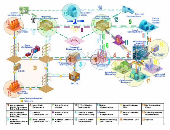
Figure 0‑22 Summary of IntelliGrid Architecture Environments
As mentioned in
the introduction to this section, IntelliGrid Architecture project is focused on defining a
set of common modeling elements to create a unified architecture that can be
universally applied to integration of utility components. The diagram below illustrates the elements of
this architecture.
Figure
0‑23 Technology Independent Architecture
Figure
0‑23 illustrates at a high level, the required aspects of
IntelliGrid Architecture design. This design is
targeted at meeting all integration for operational and analytic requirements. In this case major functional subsets of a
utility such as devices, applications, databases, and IT resources (networking
and computer hardware) share a common abstract way of communicating with each
other. This common abstraction ensures a
base level of interoperability that can be fully realized via the use of
technology profiles. On top of the
unified architecture, Device Level analysis applications can look across a
seamless collection of utility field devices as well as networking and computing
equipment to uniformly deal with lower level issues of device configuration,
status, documentation, and history.
Operations Level analysis applications enjoy a seamless view of utility
and communication operations. Tactical
business decisions focused on maximizing income and reliability can be made
knowing that all utility information is available and presented in a consistent
manner. Enterprise Level analysis
applications tend to deal with data that has been summarized with key
performance indicators highlights. The
focus here is on longer-term strategic decisions in an attempt to maximize
profitability and minimize risk. It is
imperative that analysis applications provide a concise and unified view of
utility. However, information overload
can only be dealt with a clear vision of what data is available and what
information is needed. The clarity can
only be achieved at a reasonable cost by leveraging the commonality of a
utility embodied in the IntelliGrid Architecture and the standards based approach it
advocates.
This section evaluates the existing and emerging
technologies, standards and best practices against IntelliGrid Architecture requirements and
reference model. It focuses on what technologies best enable building the new
architecture on top of what exists now and what will emerge in the future. The
recommended technologies, standards and best practices are pertaining to the
creation, storage, exchange and usage of various forms of power system
information. Specifically, they cover the following technology areas:
·
Network and System Management Technologies
·
Data Management Technologies
·
Platform technologies
·
Communication Infrastructure Technologies
·
Security Technologies
The recommendations are derived from intensive
architecture analyses. Criteria for selecting particular technologies included:
·
Satisfaction of the architectural significant
requirements as well as the common services and generic interface.
·
Market acceptance of a technology.
·
Evaluation of a technologies use in what IntelliGrid Architecture team sees as the direction of technology in general. Specifically the team sees Web based
technologies as increasing in use. Key
technologies moving forward include
o
Web Services related technologies
o
Model/ontology enabled technologies
o
Open technologies.
It should be noted that IntelliGrid Architecture team
believes that selecting individual technologies as recommended ones is not
beneficial to the industry. Rather, IntelliGrid Architecture team believes that it is better to put forward a technology independent
architecture as well as examples of how it might be implemented using existing
technologies. Consequently, the technology discussion in this section should
not be seen as singling out technologies as the ones that utilities should use,
but only as providing a structure and strategy with which utilities may make
their own choices.
Each of the five technology area subsections
contains three parts:
·
Technology analysis/evaluation
·
Technology integration
·
Analysis of gaps, overlaps, and harmonization
efforts.
Detail analysis/evaluation of technology
actually appears in appendices. This section is limited to conclusions and key
points uncovered during technology analysis.
That is, this section only contains a discussion of the capabilities of
a few key technologies as well as an overview of a comparative analysis of
current widely used ones.
The technology integration section deals with
integration issues related to the mixed use of widely used technologies. It is anticipated that most utilities will
have a non-uniform approach to the application of technology even for a similar
set of requirements. Consequently, it is
important to describe how a uniform architecture can be built in spite of this
heterogeneity.
The third part contains a description of the
identified gaps, overlaps and inconsistencies among the technologies and
standards as well as an overview of harmonization efforts occurring in the
relevant standard organizations.
As describe above, the reader needs to be
aware that different technologies are applicable to different
environments. For example, the device
level security will likely require different technologies than the enterprise
level security.
This section provides an overview of the
enterprise management technologies recommended for using with IntelliGrid Architecture. The
complete set of recommended IntelliGrid Architecture enterprise management technologies are
described in detail in Appendix D of this volume.
The entities required to be managed under
IntelliGrid Architecture range from a large number of computation-resource-limited IEDs or legacy
field devices with limited intelligence, to better equipped
substation-controller systems, to desktop and server computing systems hosting
mission-critical IntelliGrid Architecture client/server applications, to enterprise network
elements such as Local Area Network (LAN) switches and routers, to long-haul
telecommunication equipments such as SONET/SDH add-drop multiplexers
(ADMs). Given the diversity of these
managed entities and the different operational environments and requirements
they are under, no single enterprise management technology is currently able to
manage them all. In this subsection, we
will discuss a set of viable enterprise management technologies and highlight
the specific properties, which make them applicable for the management of
particular subsets of IntelliGrid Architecture managed entities under specific operational
environments. In Section 4, we discuss an approach to integrate the various
technologies and provide a unified enterprise management system.
Simple Network Management Protocol
(SNMP) is probably the most widely deployed enterprise management protocol
to-date. It was created to manage simple network components such as LAN
switches and routers. Since its inception, SNMP has been under continuous
extensions so that it can now be used for system and even application
management tasks. For example, extensions based on the operating system and
application level Management Information Base (MIBs) recently defined in IETF
proposed standards: RFCs 2287, 2564 and 2594. There also exist IETF standard
MIBs, which enable SNMP to manage computing hosts (RFC1514) as well as
relational database management systems (RFC 1697). Moreover, most IETF protocols, designed
to-date, are instrumented to be managed under the SNMP framework, e.g., the
recent IETF MIBs for the support of Multi-protocol Label Switching (MPLS)-based
traffic engineering and the management of Layer 2 and Layer 3
provider-provision virtual private networks (PPVPNs). Notice that, protocols
such as MPLS and PPVPN are particularly relevant to IntelliGrid Architecture because they are top
candidates of the key networking technologies to fulfill the end-to-end
quality-of-service (QoS) and security requirements for mission-critical IntelliGrid Architecture
applications.
Common Management Information Protocol
(CMIP) has its roots from ISO/OSI initiative and was supposed to provide better
solution than SNMP. In particular, CMIP
can support both the query of information from, and the issuing of
task-execution commands to, the managed network element. CMIP also addresses
security by providing authorization, access control and security logs ever
since its inception. Furthermore, CMIP avoids the unreliable delivery problem
of UDP-based SNMP messages by adopting a connection-oriented, reliable delivery
transport protocol. Given its roots in ISO/OSI, CMIP was designed for the
management of large-scale service provider networks. As such, it does use the
object-oriented model to allow the description of complex relationships amongst
various managed entities and the hiding (encapsulation) of implementation
details when necessary. However, the major complaint of CMIP is that it is a
product of design-by-committee and it looks better on paper than in the field.
In particular, the specification of CMIP is complex and overloaded with
numerous non-essential options. This makes the implementation and the
programming-use of CMIP very complicated. The complexity of the protocol also
translates to high computational and memory requirements of management systems
and applications supporting CMIP. The CMIP stack is large and can be of issue
on ordinary workstations or small devices. The protocol in the past has only
been supported on larger systems where the investment could be justified. In general,
the direction of the industry has been increasingly towards SNMP, even in the
public telecommunication management space, which has traditionally been the
stronghold of CMIP.
Web-Based Enterprise Management (WBEM)
is the Distributed Management Task Force (DMTF)’s approach to enterprise
management, and has three major components:
1. The
Common Information Model (CIM),
which provides an implementation-neutral common format, language and
methodology for collecting and describing management data. CIM enables common
understanding of management data across different management systems and
facilitates the integration of management information from different sources.
The DMTF CIM uses object oriented modeling principles and techniques to capture
the complex relationships and dependencies amongst various managed objects
within an enterprise. To-date, a rich set of CIM models has been proposed
and/or standardized by DMTF to model common managed entities ranging from
operating-system-free light-weight monitoring/remote-control devices, to
computer systems, to physical elements of a system, to enterprise network
elements such as LAN switches and routers, to telecommunications equipments, to
non-component-based managed entities such as a Virtual LAN or IP subnet (together
with the necessary mechanisms to deal with QoS supports in such networks), to
operating systems, to mission-critical real-time applications, to users, as
well as management policies and SLAs.
Note however that, while the DMTF CIM models available to-date already support
most of the management requirements for the non-power-utility-specific parts of
IntelliGrid Architecture, additional DMTF CIM models need to be defined to allow the management of
power-utility specific components of IntelliGrid Architecture.
2. The
xmlCIM Encoding Specification that defines, in the form of a Document Type
Definition (DTD), to represent CIM classes and object instances as XML
elements. The use of XML-based encoding takes advantage of the wide
availability of commercial XML parsing/ processing tools to further shorten
software development cycles.
3. The
CIM Operations over HTTP specification which defines a mapping of CIM
operations (i.e. method invocation on CIM objects) into HTTP so that management
systems implementing CIM can interoperate in an open standardized manner while
leveraging the ubiquitous nature of web-based technologies. The use of HTTP
also facilitates the collaboration among a federation of loosely coupled
enterprise management systems potentially belonging to separate administrative
domains, e.g. different energy providers within a same geographical area in the
case of IntelliGrid Architecture.
The key advantage of SNMP is its simplicity,
which makes it possible to instrument devices of limited computational/memory
resources to be managed via SNMP. This is also the reason why a large number of
legacy field monitoring/ controlling devices in the power-utility industries
are managed via SNMP. Owing to its simplicity and proliferation, SNMP is
supported by majority of commercial enterprise management platforms as well as
networking, telecommunications, computing and SCADA equipment manufacturers.
This makes it a popular choice for multi-vendor cross-functional enterprise
management to-date. As exemplified by the wide range of IETF MIBs mentioned
above, SNMP can be readily extended to manage additional types of entities by
adding new SNMP MIBs. The learning curve for extending SNMP via MIB addition is
not as steep as those required by other enterprise management frameworks, such
as CMIP or DMTF CIM. This is due to the simple hierarchical structure of an
SNMP MIB-tree and the lack of association between different components being
managed under the SNMP framework.
Security has been one of the key weaknesses
of SNMP. In SNMP versions 1 and 2,
authentication is supported only through a simple password mechanism. However,
since the password was sent in clear-text over the network, it is susceptible
to sniffing/ intercepting/ masquerading attacks, especially when the SNMP
message has to be delivered outside a local security perimeter. This will be of
relevance for the support of enterprise management across a federation of
administrative domains where each administrative domain may have its own
security perimeter but the communication links between the domains are not
guaranteed to be secure. Under such circumstances, additional technologies,
such as VPNs, may need to be introduced to mitigate the threat. While SNMP
version 3 addresses the security problem by introducing cryptographic
protection for the SNMP messages, it is expected that the large embedded base
of managed devices that support only SNMP V1 or V2, will continue to exist and
remain vulnerable in the near future.
SNMP was designed to model simple management
environment in which the interactions between a managed entity, i.e. a switch
or a router, with other parts of the communications/computing infrastructure of
the organization were minimal. As such, SNMP doesn’t define and specify the
associations, dependencies, and interaction relationships between different
SNMP managed entities. The lack of such interactions in SNMP has made it
unsuitable to model and thus manage large scale, complex distributed computing
environments, as found in IntelliGrid Architecture, where the end-to-end service and performance
requirements of the mission-critical distributed computing applications can
only be achieved via the integrated management and control spanning the domains
of device management, system management, enterprise network management,
telecommunications management as well as applications management. To be more
specific, one of the critical aspects of large-scale enterprise management is
the ability to capture the relationships between management classes and
objects. Since SNMP does not support object-oriented (OO) modeling, the only
available construct for specifying inter-managed-object relationships is
"group". In contrast, other modern management frameworks such as the
DMTF CIM/ WBEM, (or even CMIP to a lesser extent), provide much better support
in specifying relationships amongst managed objects via the use of OO modeling
principles and specification techniques. For example, WBEM uses the inheritance
concept in OO modeling to inherit the common shared properties between the
class of a managed object and its derived classes. The use of encapsulation
techniques found in OO modeling also helps WBEM or CMIP to make the modeling of
a complex, distributed enterprise more tractable by separating the specific
implementation details of devices/ managed systems from the its informational
and functional specifications. In this regard, SNMP does not have the construct
of "classes" to logically
encapsulate / hide related properties of a managed entity and all SNMP MIBs (or
management variables) must be listed in a large indexed table.
A disadvantage of embedded web-based
management model is its complexity, requiring ability to implement a web server
within the agents and support DMTF CIM. Some devices may not have sufficient
computing resources to allow for such features.
A limitation of both SNMP and CMIP is the
tight coupling between their network transport protocol and their
representation of management information. SNMP is defined to be transported
over UDP while most CMIP implementations are limited for OSI transport
networks. This makes them less flexible in taking advantage of advances in
alternate transport protocols. In contrast, DMTF CIM/ WBEM has consciously
separated the management information model, from its encoding, and from the
transport mechanism. This enables DMTF CIM/ WBEM to leverage the benefits of
recent encoding schemes such as XML and transport mechanisms such as HTTP and
Simple Object Access Protocol (SOAP). Such flexibility is especially important
in a heterogeneous, ever-changing environment like IntelliGrid Architecture. In particular, the
self-defining nature of XML-encoding substantially enhances the
interoperability between loosely coupled systems found across a federation of
IntelliGrid Architecture participants. The use of web-service oriented transports such as HTTP, or
HTTPS and SOAP also facilitates the secure communications across different
administrative domains within a federations, e.g. by leveraging the
firewall-traversal capability of HTTP or HTTPS and the message routing
capability in SOAP to reach destined secure message gateways along a security
perimeters.
While there has been some non-mainstream
proposals, e.g., [Chiueh 03], to
extend SNMP to be truly object-oriented and to serve as the unifying enterprise
management protocol for the next generation digitally controlled utility grid,
the technical argument lacks the support of detailed analysis. A more pragmatic
view would be to, on one hand, accept SNMP as
(1) a existing package that one needs to support in order to preserve
existing investments, and/or (2) the only viable light-weight solution for certain
types of resource-constrained managed entities such as low-cost IEDs or legacy
field devices; and on the other hand, derive a unifying management framework
which can satisfy the challenging management requirements IntelliGrid Architecture while
accommodating and interoperating with the SNMP, CMIP and other proprietary
management protocols/ frameworks. This will be the subject of the next
subsection.
In the area of networking/telecommunication
equipment management, while SNMP/RMON and CMIP both perform a similar set of
high-level enterprise management functions, there are significant
implementation complexity/cost vs. capabilities/feature trade-offs amongst
these two major protocols as discussed in Section 1.3.1.1. In practice, the
choice of management protocol is mostly dictated by the kind of management
protocol available/supported by the managed devices of interest. This is
particularly true in order to satisfy backward compatibility requirement with
the large amount of legacy-managed devices deployed in the field.
In the area of distributed application/object
management, there are overlapping technologies, such as Java Management
Extension (JMX), and CORBA-based ones, which provide similar management
functions but are designed to support particular distributed computing
platform. For instance, JMX is primarily designed for the management of
distributed application written under the Java platform although it also can be
used to enable management through Java technologies. On the other hand, there are also overlapping
application management technologies that are platform/language independent.
Examples of such include the Application Instrumentation and Control (AIC)
Standard by the Open Group, the IETF Application MIB, and the Application
Management Specification (AMS). Overlapping technologies in the desktop
management area include the DMTF Desktop Management Initiative (DMI), the IETF
Host and System MIBs
Various standardization activities are under work
to harmonize the aforementioned overlapping technologies in each area. As
discussed in Section.3.1.1, the DMTF CIM/WBEM initiative provides the umbrella
under which all the areas of enterprise management ranging from the management
of networking devices, to that of telecommunication equipment, computing
systems and application can be unified.
In particular, with DMTF CIM/ WBEM, SNMP and CMIP-based managed devices
can be managed under the framework. Recently, the TeleManagement Forum (TMF)
and DMTF also initiated a joint effort to further facilitate the convergence of
telecommunications and enterprise management by reviewing and determining
mapping between the existing models proposed by the two organizations while
partitioning new modeling/standardization efforts amongst themselves to avoid
duplicated efforts. They also pledged to work together to highlight areas for
improved integration and federation.
DMTF has also formed an Applications Working
Group to harmonize the integration of various application management standards/
initiatives to-date. These include ongoing initiatives by the Open Group
Enterprise Management Forum, the Open Group Application Quality and Resource
Management (AQRM) forum, the Open Group Application Response Measurement (ARM) working
group, the SUN Java
Community Process (JCP)
Expert group on managing J2EE environments (JCP JSR
77), the W3C Web Services Management Group as well as the Oasis Web Services
Distributed Management (WSDM) Technical Committee. This effort will also establish
the mapping between the application MIBs defined under the auspices of IETF and
the DMTF application run-time model.
Since DMTF CIM has its root for general IT
enterprise management, common information model for power-utility specific
management tasks are yet to be defined. It is critical to pursuit
standardization effort to harmonize IEC 57, 61970 CIM (i.e. the EPRI CIM) with
the DMTF CIM/WBEM framework in order to achieve an integrated energy and
communication management architecture. The existing application management
models and standards, e.g. AIC, AMS and ARM are
geared towards e-commerce applications such as online trading. Extensions of such application management
standards are needed to better support power-utility specific distributed
computing applications, such as ADA, self-healing grid, WACS/WAMS and RTP
found in IntelliGrid Architecture.
Lastly, another key missing technology is the
methodology and tool to support automatic mapping of legacy
management information model to and from modern standardized common information
model (CIM) such as the DMTF CIM. While
ontology-based experimental tools [de Vergara 03, Noy
99] of
such do exist, they still require considerable human intervention and need
substantial further development before they can be used in a real-world,
production environment.
This section provides a discussion of several
current technologies that exemplify how the IntelliGrid Architecture can be
realized. This section does not attempt
to discuss all technologies that may be used to create a unified architecture
for integration and analysis. Rather, it
only includes a discussion of a small set of technologies that demonstrate
IntelliGrid Architecture architectural issues and goals.
The complete set of recommended IntelliGrid Architecture data exchange and management
technologies are described in detail in the Appendix D of this volume.
As stated in Section 1, IntelliGrid Architecture is focused on
an architecture for integration and analysis.
This means that in general, IntelliGrid Architecture analysis treats systems as black boxes. IntelliGrid Architecture is more concerned with linking
applications as opposed to how they work internally. This significantly reduces the technologies
IntelliGrid Architecture team examines – especially with regard to data management and
exchange technologies.
A prime of example of the level of
abstraction that the IntelliGrid Architecture deals with is provided by data storage
and back up. While one would certainly
argue that reliable storage and back up of data is a key attribute of good
system design, these topics are largely out of scope of IntelliGrid Architecture because how an
application stores and backs up its data can be seen as a problem within the
application black box. Since IntelliGrid Architecture is an
integration and analysis architecture project and not a technology/development
design project, data storage and backup are out of scope.
Previous sections have explained the need for
information discovery. To discover the
structure of data, systems must agree on how data is encoded. Recently the eXtensible Markup Language (XML)
has emerged as the universal means to encode self-describing data. XML is supported by a wide variety of vendors
and has achieved a high degree of acceptance in the market place.
Information discovery also means that you can
discover meaning of data in systems.
That is, central to the notion of the unification and aggregation of
information is the notion of ontology – a term borrowed from philosophy
that refers to the science of describing entities and how they are
related. Ontology is important to
information integration since it provides a shared, common understanding of
data. By leveraging this concept we can:
·
Organize and share the entirety of asset related
information.
·
Manage content and knowledge in an
application-independent way
·
Facilitate the integration of heterogeneous data
models for the purpose of data warehousing.
Essentially, ontology is a conceptual
information model. An ontology describes
things in a problem domain, including properties, concepts, and rules, and how
they relate to one another. Ontology
allows a utility to formalize information semantics (the meaning of data)
between information systems.
The
World Wide Web and ontology
Ontology also helps solve one of the most
fundamental issues related to the Web: in order for computers to be able to use
information from the universe of web pages, information on a web page must be
put into a meaningful context. For
example, a web search on the word “rose” brings up pages related to flowers and
colors. If each page also contained a
description of how the main topics of the page fit into an ontology, then
search engines could detect if the page discussed colors or flowers.
The standardized use of a language for
ontology and its deployment on web pages would greatly expand the usefulness of
the web. In fact, the Worldwide Web
Consortium (W3C) is creating such a Web standard for an ontology language as
part of its effort to define semantic standards for the Web. The Semantic Web is the abstract
representation of data on the Web, based on the Resource Description Framework
(RDF) and it related technologies RDF Schema (RDFS) and the Web Ontology
Language (OWL). By using RDF/RDFS/OWL,
integrated and unified information systems could be made up of thousands of
subsystems all with their own internal semantics, but bound together in a
common ontology.

Figure 0‑1 RDF,
RDFS, and OWL Build on Existing W3C Work
RDF/RDFS/OWL, particular ways of using the
extensible markup language (XML), provide an application-independent way of
representing information. The RDF
related technologies build upon existing W3C work as illustrated in Figure 0‑1. RDF/RDFS/OWL
have been designed to express semantics and as opposed other technologies as
illustrated in Figure 2.
Figure 2 The
Tree of Knowledge Technologies
RDF uses XML to define a foundation for
processing metadata (metadata is information about data and is separate
from the data itself). RDF can be
applied to many areas including data warehousing, as well as searching and
cataloging data and relationships (metadata).
RDF itself does not offer industry specific vocabularies. However, any industry can design and
implement a new vocabulary.
RDF’s data model provides abstract conceptual
framework for defining and using metadata.
The basic data model consists of three object types
·
Resource : All things described by RDF
expressions are called resources, e.g. it can be an entire web page, a specific
XML or XML document or collection of whole page
·
Properties: property is a specific aspect that
describes this resource. Each property has a meaning,
·
RDF Statement (triples): A resource together
with a named property and its value.

Figure 0‑3 RDF Example
RDF
Schema (RDFS) builds on RDF and provides more support for standard semantic
concepts such as what a class, class property, and class association are as
illustrated in Figure 0‑4.
Figure 0‑4 RDFS
Example
The Web Ontology Language (OWL) builds on RDF
and RDFS to add the ability to express what is common and what is different
between different ontologies. For
example, OWL can be use to express the differences between two different energy
market ontologies defined by Nerc and ETSO for example. Specifically OWL adds:
·
Class
Axioms
o
oneOf
(enumerated classes)
o
disjointWith
o
sameClassAs
applied to class expressions
o
rdfs:subClassOf
applied to class expressions
·
Boolean
Combinations of Class Expressions
o
unionOf
o
intersectionOf
o
complementOf
·
Arbitrary
Cardinality
o
cardinality
o
minCardinality
o
maxCardinality
·
Filler
Information
o
hasValue
Descriptions can include specific value information

Figure 0‑5 OWL Example
Since
the RDF related technologies are equally suited for structured, as well as
unstructured data, like the documents described previously, they are
ideal for use as the unifying mechanism for describing data for an asset
analysis platform. These technologies
appear to be the key for next generation knowledge/content management
solutions. Using RDF/RDFS/OWL, it will
be possible to use a single information management infrastructure across all
utility information resources.
Conclusion
As described above, the most significant data
management issue revolves around how to discover the format and meaning of
data. XML and RDF provide promising ways
to describe data. However, just having
mechanisms for describing the format and meaning of data is not enough – one
must also have an understanding of the data itself as well as a means to
connect systems together in order to operate on the data. These last two tasks can be described as
technologies for understanding what data is passed and how data
is passed between systems. While XML and
RDF help us a great deal we still need Common Information Model that get
encoded using XML and RDF and Generic Interfaces complementary to XML and RDF
for application integration and data integration tasks.
If discovery of information emerges as a key
feature that a technology must support to limit configuration tasks and
increase the understanding of data, what field device protocols best support
discovery? This section discusses these
issues as they pertain to field device protocols.
Comparison
of DNP3 and IEC61850
The International Electrotechnical Commission
(IEC) Technical Committee 57 (TC57) began releasing the IEC60870-5
series of standards related to data communication protocols for intelligent
electronic devices (IED) over serial links in 1990. After several more years of
effort, the application layer protocols needed to build actual implementations
of these standards had not been finalized. Necessarily, the substation automation
division of GE-Harris in Calgary, Alberta, Canada took the existing IEC work,
finished it internally, and released it as the Distributed Networking Protocol
Number 3 (DNP3) in 1993. Simultaneously, GE-Harris formed a non-profit
organization with open membership and transferred the ownership of and
responsibility for DNP3 to this group called the DNP Users Group. The DNP Users
Group attracted a critical mass of North American suppliers and utilities as
members and supporters that resulted in DNP3 becoming widely used in North
America. The IEC TC57 continued its work and did finally release the
application protocols for serial link based communications as IEC60870-5-101 in
1994.
Figure 0‑6 The
Evolution of DNP3 and IEC61850
Both DNP3 and IEC60870-5-101 specified a
master-slave protocol for point-to-point serial links. A major consideration in
the early 90s was the relatively high cost of bandwidth for the communications
channels available to utilities. The byte efficiency of DNP3 and IEC60870-5-101
made them suitable for immediate applications in these low bandwidth
environments. Since then, as bandwidths costs have declined and as the use of
high-speed networking technology like Ethernet became widespread, even in
substations; both the IEC and DNP3 have offered Ethernet based versions of
these protocols that transmit the same byte sequences used on serial links over
high-speed local area networks (LAN)
using the TCP/IP
or UDP/IP protocols over Ethernet.
The resulting IEC standards had minor
differences with DNP3. Although seemingly minor, these differences resulted in
incompatibilities that have fragmented the market. DNP3 became very widely used
in North America and in other countries where North American suppliers had
strong market share, while IEC60870-5-101 became dominant in Europe and other
countries where European suppliers were dominant.
In 1991, the Electric Power Research
Institute (EPRI) released a specification entitled the Utility Communications
Architecture (UCA). UCA provided an
overall architecture for communications within the utility enterprise and
described the communications requirements for each application domain within
the utility enterprise. The original UCA 1.0 document referred to specific
pre-existing protocols that could be used within each application domain but
did not provide sufficient implementation details for developers to build
products around. In the distribution and transmission domains, the UCA1.0
specification suggested the use of the Manufacturing Message Specification (MMS) per
ISO9506 (released in 1988) for real-time communications. MMS was
already used in some industrial automation applications at the time and offered
high-level object oriented communications for real-time data access and
supervisory control for LAN
based devices.
In 1992, EPRI then began a process of
creating utility communications standards for real implementations in several
application spaces. The first was for control center to control center
application to replace aging bi-synchronous protocols used for inter-utility
data exchange that was needed to support the rapidly developing competitive
energy market. This resulted in the Intercontrol Center Communications Protocol
(ICCP). EPRI submitted the ICCP work to IEC TC57 Working 7 (WG07) resulting in
the IEC60870-6 TASE.2 standard in 1996. Today, ICCP-TASE.2 is widely used
world-wide for inter-utility data exchange and power plant dispatching.
Although profiles for the IEC60870-5 standards were developed for this same
application space (IEC60870-5-102), the ICCP-TASE.2 standard is more widely
used particularly in large-scale systems in North America, South America, Asia,
and Europe.
The second effort EPRI started was to fully
develop a single unified communications protocol based on the UCA1.0
recommendations for both distribution automation and substation automation
applications. This resulted in the UCA 2.0 specification which was published as
an IEEE technical report TR1550 in 1999. While the EPRI work was nearing
completion the IEC TC57 working group that developed the IEC60870-5 protocols
(WG10, WG11, and WG12) began work on upgrading the older IEC60870-5 standards
to address the needs of modern substations using LAN technologies
like Ethernet and TCP/IP.
The result was the release of IEC61850 in 2003 that integrated the European
experience with IEC6087-5 with the North American efforts of UCA2.0 to create a
single unified international standard for substation automation utilizing
modern high-speed networking technology.
IEC61850 specifies a set of communications
requirements for substations, an abstract service model for commonly required
communications services in substations, an abstract model for substation data
objects, a device configuration language based on XML, and a mapping of these
abstract models to the MMS
application layer protocol running over TCP/IP
based Ethernet networks. The
virtualized architecture of the IEC61850 standard (whereby an abstract model
for services and objects are mapped onto a specific protocol profile) provides
a flexible approach that could, theoretically, be mapped onto other protocols
in the future.
The most significant differences in the roots
of DNP3 (including IEC60870-5) and IEC61850 is that DNP3 was originally defined
as an RTU protocol for low-bandwidth point-to-point serial link requirements
that was later migrated for use over high-speed substation networks. IEC61850
was designed specifically for application in the substation LAN
environment. Most of the technical differences between these protocols can be
directly traced to these different roots. Some would argue that having a single
simpler protocol work over both serial links and LAN can
reduce costs by reducing the learning curve associated with deploying new
protocols. Others will argue that using simple serial link protocols originally
intended for low bandwidth environments does not take advantage of the
capabilities of modern networks and IEDs and results in lower performance with
higher configuration and maintenance costs.
Comparison
of Communications Profiles
Although DNP3 was originally developed for
serial link profiles, the DNP Users Group (and IEC TC57 for the IEC60870-5
standards) have released communications profiles that enable DNP3 to operate
over Ethernet based networks. While the UCA2.0 specification provided both
serial link and Ethernet based profiles, the IEC61850 standard provides
profiles for Ethernet based networks only. The comparison provided here will
focus on the Ethernet based profiles for DNP3 and IEC61850.
There are two types of Ethernet based
communications profiles supported by these standards: connection-oriented and
connectionless. A connection-oriented profile is used to support directed communications
where there is a virtual connection between two communicating entities and only
two entities per communications session. Connectionless profiles are typically
used for multicast messaging where a single transmitted message can be received
by multiple receivers. Both IEC61850 and DNP3 offer separate profiles for
connection-oriented and connectionless communications.
Figure 0‑7 Profile Comparison: Directed Communications – Connection-oriented
For the connection-oriented profiles, both
IEC61850 and DNP3 utilize TCP/IP
protocols for the transport and network layers. For the DNP3 profile, the same
master-slave protocol that was developed for the serial link profile, including
DNP3 Pseudo Transport and Data Link protocols, is sent over TCP. TCP
connections are initiated between the master and each slave on the network.
DNP3 slaves listen on a defined TCP port
for incoming messages from the master. Upon receipt they would respond to the
master appropriately. Like in a serial based system, the DNP3 data link is used
to coordinate the activities between masters and slaves. There are DNP3 data
link protocol packets that are received by slaves that tell them when they can
either respond to a message from the master or when they can send unsolicited
data for reporting purposes. Although the coordination of this activity is not
strictly required by the underlying TCP/IP
stack, this approach enables existing master and slave software to be used for
both serial and LAN
profiles without a lot of modification. The result is a master-slave protocol
running on the peer-to-peer TCP/IP
network.
IEC61850 uses an Internet Engineering Task
Force (IETF) standard called RFC1006 for mapping the IEC61850 and MMS
protocol packets over a TCP/IP
network for connection-oriented communications. The RFC1006 standard was
developed by IETF for mapping ISO/OSI
application level protocols, like the MMS that
IEC61850 is based upon, to TCP/IP.
In IEC61850 a calling node issues a connection request to a remote called
node. Called nodes listen for incoming connection requests on a defined TCP
port. Once the communications session has been established either side may
assume the client or server role and send data and/or requests over the
connection independently of the other side as long as the connection is up.
Figure 0‑8 Profile Comparison: Multi-cast communications – Connectionless
For connectionless communications, DNP3 and
IEC61850 differ more substantially. As with the connection-oriented profile,
the DNP3 profile for connectionless essentially runs the DNP3 serial link
profile over an Ethernet based profile. In this case, the Unsolicited Datagram
Protocol (UDP) protocol is used instead of the TCP
protocol. UDP is a connectionless non-reliable transport protocol that provides
connectionless communications over IP based networks. Reliable message delivery
is provided by the DNP3 Pseudo Transport and Data Link protocols that are used
in this profile. Rather than listening on a defined TCP port
for incoming messages from a master, DNP3 slaves listen to a multi-cast IP
address for messages from the master. Both slaves and masters need to be
configured with the multi-cast IP address. Because UDP is not a reliable
message transport protocol that supports segmentation and reassembly of
packets, there are some limitations about how data can be transmitted using
this profile. For some applications, these limitations may not be significant
and there are successful implementations of this profile.
For IEC61850, and unlike DNP3, the
connectionless multi-cast profile serves a fundamentally different purpose than
the connection-oriented profile. With IEC61850 the connection-oriented profile
is used at the station level for data exchange between two specific nodes. In
the connectionless profile IEC61850 uses the multi-cast profiles to send
several fundamentally different types of messages to multiple nodes
simultaneously: 1) status information (Generic Substation Status Event – GSSE)
regarding the state of an IED, 2) data set of IEC61850 objects (see discussion
of object models later), and 3) sensor information via the Sampled Measures
Values (SMV) approach
of IEC61850-9-2. GSSE is typically used by protective relays to broadcast their
current status (e.g. blocked, tripped, etc.) quickly (≤4 milliseconds) so that other
devices can use that information in complex protection algorithms. A Generic
Object Oriented Substation Event (GOOSE) is used to communicate commonly used
information (e.g. three phase voltage measurements) to multiple nodes
simultaneously. SMV is
used to send raw measurements from intelligent sensors to multiple nodes
simultaneously that enables a digital replacement for analog current and
voltage transformers.
In summary, the DNP3 profiles enable the
transmission of the same protocol originally developed for serial links over
either connection-oriented or connectionless LANs. This results in the
essential character of the protocol being preserved (i.e. master-slave) while
supporting the very significant performance improvements that the use of modern
LAN
technology affords. The only real difference in the DNP3 connection-oriented
versus connectionless environments is that the latter avoids the small TCP
overhead of maintaining separate TCP
connections between each master and slave. The IEC61850 connection oriented
profiles offer a similar capability as the DNP3 profiles offer for basic station
level and SCADA services using a client-server approach that enables
independent communications between nodes. IEC61850 connectionless profiles
support other capabilities for specific substation applications that go beyond
the original intent of DNP3.
Comparison
of Service Models
The services supported by DNP3 is large
subset of that offered by IEC61850. This is not surprising since both are
intended for similar applications in substation automation. In several areas
where either DNP3 or IEC61850 has a capability not supported by the other, it
is still possible to implement these services by combining other services. For
instance, event logs can be implemented using files in DNP3 even though the
DNP3 standard does not specify how to implement event logs. While the advantage
of having the standard define these capabilities directly might be lost, the
basic functionality is still available.
Figure 0‑9 Service Comparison
There are services that IEC61850 offers that
cannot be practically supported using the current version of DNP3. These
services include object discovery, Substation Configuration Language (SCL),
GOOSE, GSSE, and SMV.
Because these high-level (object discover) or very high-performance (GOOSE,
GSSE, and SMV)
services were not practical for low-bandwidth serial link applications, they
were never a part of DNP3’s origins and, therefore, were not available for the LAN
based profiles that were developed for DNP3. There are work items within the
DNP Users Group to develop a mapping between the abstract models of IEC61850 to
DNP. However, such a mapping would require protocol changes to support these
additional services that could not be implemented using the DNP3 protocol as it
is defined today.
Comparison
of Object Models
Both IEC61850 and DNP3 define various objects
for representing power system data. The DNP3 object model is based on a
traditional remote terminal unit (RTU) device model. A traditional RTU is
general purpose device capable of collecting I/O signals in a variety of
formats (digital, analogy, state, etc.) and communicating those I/O points
using a given SCADA protocol, like DNP3. Because RTUs were traditionally
general purpose, it was the user or system engineer that determined the
specific function a specific I/O point represented when they wired that I/O
point within the substation. For example, an RTU would have a variety of analog
and digital inputs. It was typically the user that wired those inputs to
specific current and voltage transformers or specific breakers that created the
“mapping” between these I/O points and specific functions in the substation.
Therefore, when the engineer wanted to access the I/O for a given bus voltage
by communicating to the RTU from a remote site via some protocol, they would
have to have either a wiring diagram, or other document, that described where
the desired voltage was wired into the RTU in order to access that I/O point
via the RTU protocol.
The DNP3 data model is based on a similar
structure. A DNP3 object description is comprised of three different parts:
·
Object Number. The object number
specified the type of data point using a numerical value. For example, object
number = 1 would represent a Binary Input Static data point, object number = 2
would represent a Binary Input Event data point, and so on.
·
Variation Number. The variation number specified which optional
parameters would be present for a given data point of a specific object number.
For instance, variation number = 1 would mean that the data point included
status, variation number = 2 meant that the data point did not include status,
and so on.
·
Index Number. The index number refers to
a specific instance of an object of a given object and variation. For instance,
if a device supported 16 binary input static objects, the index number to
access one of these was 0-15.
·
Device Profile. In addition to the
description of the data points as defined above, the DNP Users Group also
specified device profiles for common devices that specified which objects
should be implemented for a given type of device with recommendations for which
object and variation numbers should be used for various types of signals that
are commonly needed in these applications.
The result is that DNP3 specified a broad set
of data objects and device types sufficient to provide interoperability for a
large number of applications and device types in power systems. Additional
profiles are added as needed by the user community. Furthermore, the use of
small 8-bit numbers to represent object and variation types and compact index
numbers provided a very byte-efficient mechanism for specifying a data point.
This allowed DNP3 to maximize the number of data points that could be fit into
a single DNP3 data frame. As described earlier, this byte efficiency was
critical to the effectiveness of DNP3 as a solution for low-bandwidth serial
links.
The IEC61850 data model is an object oriented
model that not only defines the basic data types for common data points, but
also rigorously defines the naming conventions used and how the data is
organized into functional groupings called logical nodes. IEC61850 does
not use compact numbers to describe data points. Instead, IEC61850 uses names
that specify a fixed hierarchical organization for the data to describe each
data object. The name specifies not the only the way you access the data point
via the protocol, but it also defines its functional characteristic within the
device. In other words, the engineer can determine that a given point is a
voltage without having to know how the device is wired. The IEC61850 data model
consists of the following concepts:
·
Logical Device. The IEC61850 object model
enables a single physical device to represent data for multiple logical devices
such as might exist in a data concentrator application. This name is typically
defined by the user or supplier. IEC61850 requires at least one logical device
with a name of “LD0” to be present to hold data common to all logical devices
such as device identity information.
Figure 0‑10 IEC61850 Object Model
·
Logical Node. Specifies a grouping of
data objects that are functionally related. For instance, measurements are contained
in logical nodes with the name “MMXU”, data related to a switch controller
function will be contained in logical nodes with the name “CSWI”, breaker data
will be contained in a logical node named “XCBR”, and so on. Multiple instances
of the same logical node are delineated by a suffix number (MMXU1, MMXU2,
etc.). Logical nodes that are related to each other (the switch controller
(CSWIx) associated with a given breaker (XCBRx)) are associated to each other
in the name using a user defined prefix.
·
Functional Constraint. While not a formal part of the object models
for IEC61850, the mapping of IEC 61850 to MMS
contained in part 8-2 introduces this name to group together data objects with
similar functions within the logical node. For instance, “MX” designates
measurements and “DC” designates descriptions, etc.
·
Data Object. The data object name
specifies the data desired. For instance, “V” specifies voltage and “A”
specifies current, etc.
·
Attributes. These specify the individual
elements that comprise a data object. For instance, “PhsAf” specifies the
floating point value for phase A in a wye-connected measurement, “q” specifies
quality flags, “t” specifies the time stamp, etc. The IEC61850 standard defines
the data types (integer, floating point, binary, time, etc.) for all allowable
attributes.
Per the mapping of IEC61850 to 8-1, to create
an object name you would take each element from the Logical Node down in the
hierarchy separated by dollar signs (“$”). Therefore, the floating point value
of the phase A voltage in the first measurement unit of a given device would
be: MMXU1$MX$V$PhsAf. A power system engineer familiar with the IEC61850 naming
convention can determine which data point contains the data they are interested
in by examining the same name that is used to access the data via the protocol.
The name for the same functional objects is mostly the same in any given device
regardless of the brand or type of device.
Additionally, IEC61850 includes a Substation
Configuration Language (SCL per
IEC61850-6) that can be used to express the configuration of all the data
objects in a given device using XML. An SCL file
will contain a description of all the logical devices, logical nodes, etc. that
are defined for a given device. The SCL file
can be used for many purposes that can significantly lower costs and improve
productivity including: enabling users to create specifications for devices
that can be used for RFPs to ensure the equipment they purchase meets their
functional requirements, automated tools can be developed to automatically
configure devices with specific objects, configuration information on devices
can be exchanged among devices improving the interchangeability of devices and
applications, and many other future uses limited only by the creativity of
users and suppliers.
Conclusion
In many ways, a direct head to head
comparison between DNP3 and IEC61850 is not fair, and depending on the
circumstance, might not even be valid. It is a classic apples and oranges
comparison. You can use apples to make applesauce and you can use oranges to
make orange juice. But there is no reason that you can’t enjoy a glass of
orange juice while eating a bowl of applesauce. The same is true with respect
to DNP3 and IEC61850: they are not mutually exclusive. Each protocol has
characteristics that will make it optimal for a given set of application
constraints. Each was designed to be optimized for a given set of requirements.
This does not mean that neither can be used outside of its optimal space nor
does it mean that only one or the other can be used at any given time. The byte
efficiency of DNP3 makes it an excellent choice for bandwidth constrained
applications in distribution like pole-top devices or where existing systems
already provide DNP3 connectivity. The
high-level object models and high-performance services of IEC61850 will make it
an excellent choice where large numbers of devices must be configured, where
the number of communicating entities is difficult to fix or is constantly
changing, and where changes in device configuration is frequent cause
maintenance problems in existing applications. Any well-designed system will
utilize each/both DNP3 and IEC61850 as appropriate to maximize the benefits and
minimize the costs for implementing the systems needed by users.
Key technologies
for the integration and analysis of control center data are three IEC
standards: WG 13’s 61970 Common Information Model (CIM) and Generic Interface
Definition (GID) as well as WG 14’s 61968 messaging
standards. How these standards fit in
with other TC 57 standards is illustrated in Figure
0‑11
Figure 0‑11 TC
57 Standards
IEC CIM
The CIM contains
object types such as substations, breakers, and work orders as well as other
data typically found in an EMS,
SCADA, DMS, or work, and asset management system. More recently, the CIM is
being extended to include transmission reservation and energy scheduling
information. The CIM was originally developed as part of the EPRI Control
Center Application Programming Interface (CCAPI) project and later standardized
by IEC TC57 WG13 as part of the IEC61970 series standards for control centers.
The CIM standard includes information associated with control center
applications such as:
·
Energy Management Systems (EMS)
o
Topology Processing
o
State Estimator
o
Power Flow
·
Security Analysis
·
Supervisory Control and Data Access Systems
(SCADA)
·
Network planning
IEC TC57 WG14 has
extended the CIM in their IEC61968 standard for Distribution Management Systems
(DMS) related functions. IEC61968 added information models associated with
operational support applications such as:
·
Asset Management Systems (AMS)
·
Work Management Systems (WMS)
·
Construction Management
·
Distribution Network Management
·
Geographic Information Systems (GIS)
·
Outage Management
The CIM describes
real world objects in terms of classes, attributes and relationships. For
example, the diagram below depicts the relationship between a set of CIM
classes per IEC61970. A substation can contain voltage levels. Voltage levels
can contain equipment. Breakers and Transformers are subtypes of a more general
class called Conducting Equipment. Breakers have terminals that are associated
with measurements. Transformers have windings that are also associated with
measurements. And so on.
Figure
0‑12 Simplified Fragment of CIM Power System Model
This diagram above
does not illustrate all the possible associations specified in CIM. For
example, substations, breakers, and transformers may also be directly
associated with measurements. The
diagram below illustrates a very simplified view of some of the CIM classes
added by IEC61968:

Figure
0‑13 Simplified Fragment of CIM Asset/Work Model
In the diagram
above, Power System Resource is the parent class of all logical equipment, such
as circuit breakers, and equipment containers, such as a substation. In the
CIM, the term “asset” refers to a physical object. Assets are associated one to
one with logical equipment. Assets exist at a location that can be represented
on a map. Elsewhere, the IEC61968 CIM also defines a parent document class.
Outage reports, equipment lists, work orders, and inspection schedules are sub
types of the document class. An outage report contains an equipment list that
refers to one or more assets. And so on.
The CIM is defined
as a set of Class Diagrams using a model language called the Unified Modeling
Language (UML). UML is an object-oriented modeling language used for system
specification, visualization and documentation. UML is a way of describing
software with diagrams and is a language that both users and programmers can
understand. The CIM itself is maintained in a software information modeling
tool called Rational Rose. This is just one of many tools supporting UML.
The CIM is partitioned into a set of packages.
Each package is a way of grouping related model elements. Each package in the
CIM contains one or more class diagrams showing graphically all the classes in
that package and their relationships to other classes. Measurements are defined in the Meas
package, which contains entities that describe dynamic measurement data
exchanged between different applications.
The CIM class
diagrams describe the types of objects in the system and the various kinds of
static relationships that exist among them. There are three principle kinds of
static relationships:
·
Associations (A Terminal is connected to a
connectivity node)
·
Generalization and subtypes (A switch is a type
of conducting equipment)
·
Aggregation (A winding is part of a transformer)
Generalization or
inheritance is a powerful technique for simplifying class diagrams. The primary
use of generalization in the CIM is shown in figure below.
Figure
0‑14 Generalizations for power system resource and conducting
equipment
By defining a
PowerSystemResource class, the attributes and relationships for this class can
be inherited by all the other subclasses. The PowerSystemResource class is used
to describe any physical power system object or grouping of power system
physical objects that needs to be modeled, monitored or measured. All the
subclasses of PowerSystemResource inherit the following relationships:
·
PowerSystemResource “measured by” Measurement
·
PowerSystemResource “owned by” Company
·
PowerSystemResource “member of” PowerSystemResource.
The
ConductingEquipment class is used to define those objects that conduct
electricity. As shown in the figure below,
the following associations are used to specify the connectivity of these
objects:
·
ConductingEquipment “has” Terminals
·
Terminal “is connected to” ConnectivityNode
·
Connectivity Node “is member of” TopologicalNode
Figure
0‑15 Defining connectivity for conducting
equipment
The transformer
model in the figure below illustrates the use of Aggregation. The aggregation
relationship specifies that:
·
A Transformer “has” one or more windings
·
A Transformer Winding “has” 0, 1 or 2 Tap
Changers
Figure
16 Transformer model illustrating use of
aggregation
In the CIM, the
aggregation relationships in the figure above would be specified using the
PowerSystemResource “is member of” PowerSystemResource relationship. Equipment
can be grouped into zero, one, or several containers. For example, a switch
could have the following relationships:
·
Switch “is member of” substation
·
Switch “is member of” transmission line
·
Switch “is member of” Feeder
Comparison of the CIM and the 61850
Object Model
There is often
understandable confusion about the similarities and differences between the
IEC61850 device object models and the IEC61970 CIM UML-based Models. Both are
abstract models of information; both involve utility operations; both were
developed in the IEC TC57 standards organization in two working groups with
some common membership. Both object models are defined using XML schemas. Yet
despite these similarities, they have not (yet) been “harmonized” to work
together as a seamless whole.
Figure 17 provides an overview of the domains of the two
standards.

Figure
17:
IEC61850 Models and Connections with IEC61970 Models
IEC61850
As can be seen in
this figure, the IEC61850 models are predominantly in the field. These IEC61850
models are of physical field devices, such as circuit breakers,
protection relays, capacitor controllers, and, in recent work, distributed
energy resources such as wind turbines, diesel generators, and fuel cells. The
IEC61850 standard contains a number of parts, including the actual Object
Models (OM), Service Models (SM), and mappings to different Communication
Protocols (CP).
The Object Models
are “nouns” with pre-defined names and pre-defined data structures. Objects are
the data that is exchanged among different devices and systems. The OM
structure from the bottom up is described below:
·
Standard
Data Types: common digital formats such as Boolean, integer, and floating
point.
·
Common
Attributes: predefined common attributes that can be reused by many
different objects, such as the Quality attribute. These common attributes are
defined in IEC61850-7-3 clause 6.
·
Common
Data Classes (CDCs): predefined groupings building on the standard data
types and predefined common attributes, such as the Single Point Status (SPS),
the Measured Value (MV), and the Controllable Double Point (DPC). In essence,
these CDCs are used to define the type or format of Data Objects. These CDCs
are defined in IEC61850-7-3 clause 7.
·
Data
Objects (DO): predefined names of objects associated with one or more
Logical Nodes. Their type or format is defined by one of the CDCs. They are
listed only within the Logical Nodes. An example of a DO is “Auto” defined as
CDC type SPS. It can be found in a number of Logical Nodes. Another example of
a DO is “RHz” defined as a SPC
(controllable single point), which is found only in the RSYN Logical Node.
·
Logical
Nodes (LN): predefined groupings of Data Objects that serve specific
functions and can be used as “bricks” to build the complete device. Examples of
LNs include MMXU which provides all electrical measurements in 3-phase systems
(voltage, current, watts, vars, power factor, etc.); PTUV for the model of the
voltage portion of under voltage protection; and XCBR for the short circuit
breaking capability of a circuit breaker. These LNs are described in IEC61850-7-4
clause 5.
·
Logical
Devices (LD): the device model composed of the relevant Logical Nodes. For
instance, a circuit breaker could be composed of the Logical Nodes: XCBR, XSWI,
CPOW, CSWI, and SMIG. Logical Devices are not directly defined in any of the
documents, since different products and different implementations can use
different combinations of Logical Nodes for the same Logical Device. However,
many examples are given in IEC61850-5.
IEC61970
In contrast, the
IEC61970 CIM models are predominantly in the control center, where the core
model is of the relationships among the power system elements, such as
what transmission lines are connected to which substations, which are connected
to which circuit breakers and distribution lines. The CIM provides an abstract
model of power systems, including physical configuration (wires), political
aspects (ownership hierarchy), market aspects, and others. It is defined in UML
and can be represented in XML. The GID, also defined as part of IEC61970, provides
abstract services for exchanging objects, including read/write and
publish/subscribe. The fact that these are abstract
means that they are technology independent, and can be implemented using
different technologies in different installations.
CIM limitations
include that the CIM model is static, so that definitions of data exchanges in
CIM format are not a part of the CIM model and must be defined externally for
each implementation. No mechanism is included in the standard to define data
exchanges dynamically, although the Component Interface Specifications describe
some specific types of CIM objects to be exchanged for specific functions. In
addition, CIM is focused on transmission power system and asset management
applications, and therefore, still requires extensions for other aspects of
power system operations.
IEC61850 Configuration
Language and the CIM
The concept of a configuration
language is that the configuration of the substation can be modeled
electronically using object models, not just the data in the substation. This
model of the substation configuration allows applications to “learn” how all
the devices within a substation are actually interconnected both electrically
and from an information point of view.
The Substation
Configuration Language (SCL), IEC61850 Part 6, defines the
interrelationship of the substation equipment to each other and to the
substation itself. Although the substation object models define each of the
devices in the substation, these device models do not define how the models are
interrelated. Therefore Part 6 was developed to provide a tool for defining the
substation configuration.
The SCL uses a standard file format for exchanging
information between proprietary configuration tools for substation devices.
This standard is based on Extensible Markup Language (XML), and draws on the
data modeling concepts found in the other parts of IEC 61850, and the
capability of the IEC 61850 protocols to “self-describe” the data to be
reported by a particular device.
The SCL is therefore almost identical in concept to
the CIM: it is identifying the relationships
among the different devices within the substation. It is exactly here where the
main “conflict” between the two standards emerges.
Harmonization
In one sense,
these differences between the two models are as great as those between apples
and oranges. However, it is clear that both are needed and that each
supplements the capabilities of the other. In addition, if both are implemented
in a utility, they must interface with each other and function as an integrated
whole.
The IEC TC57 has
in fact undertaken to harmonize the two models as illustrated in Figure 0‑18.
Figure
0‑18 Proposed Harmonization of 61850 and 61970
Information Models
In this on-going
harmonization work, two Use Cases were identified as being important in
illustrating the key harmonization issues:
·
‘Retrofit of the equipment in a substation (with
addition of a new line and transformer)’
·
‘Real-Time information exchange between 61850
devices and the Control Center / Office’
The first Use Case
assumes the use of the Substation Configuration Language in the IEC61850 world,
and addresses the harmonization between that and the CIM. Since both SCL and CIM use XML, some preliminary work has
suggested adding SCL to the CIM as another UML sub-model, with
the IEC61850 Logical Nodes identified via XML tags that have been harmonized
between the CIM and SCL. Some naming issues remain.
The second Use
Case addresses a secondary “conflict” which is that the CIM defines all
measurements as “PowerSystemResource” combined with a “MeasurementType” with no
further clarification, while IEC61850 defines each value with a unique name.
Although not formalized yet, the solution seems to be to use the CIM AliasName
in the MeasurementType CIM table to refer to the IEC61850 names.
61970 Generic Interface Definition
Without a means to
discover what data an application processes, plug and play is nearly impossible
to achieve. To address these impediments
to plug and play and the need for a common exchange mechanism, or “how” data is
exchanged, WG13 is in the process of adopting a series of interface standards
called the Generic Interface Definition (GID). The GID is an umbrella term for four interfaces:
·
Generic Data Access (GDA) – A generic
request/reply oriented interface that supports browsing and querying randomly
associated structured data – including schema (class) and instance information.
·
Generic Eventing and Subscription (GES) – A publish/subscribe oriented interface
that supports hierarchical browsing of schema and instance information. The GES is typically used as an API for publishing/subscribing to XML formatted
messages.
·
High Speed Data Access (HSDA) – A request/reply
and publish/subscribe oriented interface that supports hierarchical browsing
and querying of schema (class) and instance information about high-speed data.
·
Time Series Data Access (TSDA) – – A
request/reply and publish/subscribe oriented interface that supports
hierarchical browsing and querying of schema (class) and instance information
about time-series data.
Table 0‑1 below organizes the GID functionality into a simple matrix:
|
Table 0‑1 Matrix Of GID
Functionality
|
|
|
Generic
|
High Speed
|
Time Series
|
|
Request/Reply
|
GDA
|
HSDA
|
TSDA
|
|
Publish/Subscribe
|
GES
|
HSDA
|
TSDA
|
Applications use
the standard interfaces to connect to each other directly or to an integration
framework such as a message bus or data warehouse. The GID interfaces allow applications to be written
independently of the capabilities of the underlying infrastructure.
The GID can be realized using a variety of
middleware technologies including:
·
RPC/API based CORBA, COM, Java, or C language
specializations
·
W3C Web Services/XML/HTTP based
Regardless if
these interfaces are implemented as an API or on the wire, the GID provides the following key functionality
required for creation of a plug and play infrastructure:
o
Interfaces are generic and are independent of
any application category and integration technology. This facilitates
reusability of applications supporting these interfaces.
o
Interfaces support schema announcement/discovery
– The schemas are discoverable so that component configuration can be done
programmatically at run time. Programmatically exposing the schema of
application data eliminates a great deal of manual configuration.
o
Interfaces support business object namespace
presentation – Each component describes the business object instances that it
supports within the context of a common namespace shared among all applications
such as a power system network model like the EPRI Common Information Model
(CIM). It is not enough to merely expose the application data schema, one must
also expose what specific breakers, transformers, etc., that an application
operates on. This also eliminates manual
configuration as well as provides a means for a power system engineer to
understand how enterprise data is organized and accessed.
The advantage of
using generic interfaces instead of application-specific ones cannot be over
emphasized. The benefits of using
generic interfaces include:
The interfaces
developed are middleware neutral and were designed to be implemented over
commercially available message bus and database technology. This means a single wrapper can be used
regardless on the technology used to perform integration.
As application
category independent, the same interfaces are used to wrap any
application. This means that new
wrappers do not need to be developed every time an application is added to the
system.
·
Creates a consistent and easy to use integration
framework by providing a unified programming model for application integration.
·
Enhances interoperability by “going the last
mile”. Agreement on the “what” of data is not enough to ensure component
interoperability. We also need to standardize on “how” data is accessed. To
provide a simple analogy, we standardize on a 110/220 volt 60 hertz sine wave
for residential electrical systems in the US. This is a standardization of
“what”. However, we also standardize the design of the plugs and receptacles.
This is a standardization of the “how”. The standardization of plugs and
receptacles means that we don’t need to call an electrician every time we want
to install a toaster. Similarly with software, standardizing on the interface
means a connector does not need to be created from scratch every time we
install a new application.
·
Since application vendors can “shrink wrap” a
CIM/GID compliant wrapper, the use of the CIM and GID can lower the cost of integration to
utilities by fostering the market for off-the-shelf
connectors supplied by application vendors or 3rd
parties. The time and money associated with data warehousing/application
integration wrapper development and maintenance is high. Typically, most money
spent on integration is spent on the wrappers. An off-the-shelf CIM/GID wrapper can replace the custom-built
“Extraction and Transformation” steps of an Extraction/Transformation/Load
warehouse process. The availability of off-the-shelf CIM/GID compliant wrappers is a key to lowering
application integration and data warehouse deployment and maintenance costs
very significantly.
The GID interfaces support viewing of legacy
application data within the context of a shared model such as the CIM. The GID interfaces take full advantage of the fact
that the CIM is more than just a collection of related attributes – it is a
unified data model. Viewing data in a CIM context helps eliminates manual
configuration and provides a means for a power system engineer to understand
how enterprise data is organized and accessed. The GID interfaces allow legacy data to be exposed
within a power system oriented context. This makes data more understandable and
“empowers the desktop” by enabling power system engineers to accomplish many
common configuration tasks instead of having to rely on IT personnel.
Namespaces
The GID interfaces specify two related mechanisms.
The first specifies a programmatic interface that a component or component
wrapper must implement. The second specifies how a populated information model
such as the CIM (the power system class metadata specified in the information
model as well as the related instances) is exposed via the programmatic
interface. The later concept is embodied in the term “namespace”.
A namespaces can
include a complex set of inter related metadata and related instance data. In this case, the namespace contains a “mesh
network” or “lattice” of nodes as shown in Figure
0‑19. In other
words, there is more than one path between any two nodes so it is hard or
impossible to say there is a top or bottom.
The display of all of an unpopulated (just object types) or populated
(including object instances) CIM provides two examples mesh networks since many
CIM classes have many associations to different nodes.

Figure
0‑19 Example of a Full Mesh type of Namespace
The TC57 standard
namespaces provide an agreement on how to communicate CIM based hierarchies
via an interface that supports namespace browsing such as the GID and supply a utility specific way (CIM
based) of viewing and configuring the exchange of data. That is, the TC 57 standard namespaces
provide a restricted means for exposing the CIM schema and instance data an
application processes.
Three hierarchical
namespaces are standardized in 61970. They are:
·
TC57PhysicalModel
·
TC57ClassModel
·
TC57ISModel
The
TC57PhysicalModel is a tree that orders power system related instance data in
accordance to how it is contained from a physical perspective. Companies contain
sub control areas; sub control areas contain substations, etc. The idea is that
a power system engineer can find a breaker without having to remember a
potentially convoluted or inconsistent naming scheme as shown below.
Figure
0‑20 Example TC57PhysicalNamespace
The TC57ClassModel
consists of a tree that orders power system related instance data in accordance
to object types. Viewing data is this way is often most convenient for example
when one wants to access all protective relays for example.
Figure
0‑21 Example TC57ClassNamespace
The TC57ISModel
namespace is associated with the Generic Eventing and Subscription (GES) interface, the standard interface for
publishing and subscribing described below. The tree allows an application to
describe what message types (application data schema) it publishes as well as
the content of each message type.

Figure
0‑22 Example TC57ISNamespace
The use of namespaces
This section
describes how a namespaces can be used at an application interface to make
utility data more understandable and usable. For example consider the diagram
below:

Figure 0‑23 Traditional
view of utility data
Figure 0‑23 shows how data is often presented by a typical legacy
application. In this case customer data is presented by an application as a
flat set of records without much information about how customers relate to
information modeled in the CIM such as network topology or maintenance history.
However, if one is interested in correlating the reliability of power delivered
to customer to repair records or a network element such as a distribution
feeder for example, then it is useful to be able to put customer records in the
context of the model. The generic interfaces provide a standard way of exposing
data such as customer records within a namespace, in this case the
TC57PhysicalModel as illustrated in Figure
0‑24:
Figure
0‑24 Customer data within a CIM Network View
The GID interfaces provide the capability to
discover the metadata and instance data a server exposes via browsing. However, browsing a server’s complete
namespace may consume a large amount of time. For example, consider a namespace
deployed at a large utility. If one
counts all the measurements in the namespace, the number might exceed one
million. The number possible paths to
these measurements can be an order of magnitude more. This can significantly degrade the client
user experience. It is not efficient to
individually discover each measurement by browsing the namespace. Rather, it
would be better if a client that wishes to subscribe to measurement data
updates could determine the locations (paths from a hierarchical namespace root
to destination) of each measurement in a more efficient way. But how can this be done when there is no
standard way of naming each measurement point that indicates where a
measurement occurs in a power system model.
The solution is provided by the employment of a known common information
model such as the CIM and a standard namespace such as the TC57PhysicalModel
namespace.
Consider the
simple namespace illustrated in Figure
0‑25. In this
example with regard to metadata, it is possible for a company to own or operate
a device and devices can have measurements associated with them. With regard to instance data, Eastern
Electric is a company that owns TransformerABC that has a temperature
measurement called Point7.
Figure
0‑25 Example Full Mesh Namespace
From this full
mesh namespace, at least two different hierarchical namespaces could be
constructed: one that specifies “company owns devices which have temperature
measurements” and another that specifies “company operates devices which have
temperature measurements”. Since both
are possible it is impossible for an off the shelf client application to
quickly discover the paths from root to every measurement for a large full mesh
information model. On the other hand, if
the client can assume a known hierarchy say “company owns devices which have
temperature measurements”, then the client can perform a very limited number of
queries to discover all the paths to all measurements. In this very simple example, a client need
only query twice once configured with the company name. In the case of the CIM, agreement on the
inclusion of only a limited set of associations that can be traversed can
dramatically improve the user wait time for a client discovering measurements
in a large namespace.
Another example of
the use of the TC57Namespaces consists of the possibility to completely
automate SCADA data client subscription from a TC57Namepace compliant SCADA
server if the client application can import the complete model from a power
system model provider such as an EMS. In this case, a client has the capability
to automatically build the paths to all the measurements in SCADA Server. The
server side of this use case has been tested during the EPRI sponsored CIM/GID Interoperability testing.
An additional
benefit of providing customer data in a standard namespace is that off the
shelf components can be created independently of individual customers
requirements. Such standardization is necessary if one hopes to foster a market
for off the shelf applications.
The Generic Interfaces
Rather than
inventing new interfaces, the IEC chose to leverage OPC - a set of widely deployed de facto standard
interfaces frequently used in the process control industry and supported by
close to 1000 vendors. Three out of four of the IEC interfaces incorporate the
equivalent the OPC interface. However, since the OPC interfaces were originally based on
Microsoft specific technology, the IEC also decided to leverage cross platform
versions of the OPC interfaces standardized in the Object
Management Group (OMG). The OMG is a software standards consortium
consisting of all major software vendors. The OPC versions of the IEC interfaces are used when
deploying COM, .Net or Web Services based interface technology so that the
hundreds of OPC clients available off the shelf from many
vendors are GID compliant today. On the other hand, the OMG version of the GID is use to define the CORBA, Java, or C
Language interfaces. The diagram below illustrates the lineage
between the WG 13, OMG, and OPC interfaces.
Figure
0‑26 Interface Lineage
While for the sake
of convenience, this document will use the IEC names when discussing the
Microsoft and non-Microsoft varieties of the interfaces, it should be noted
that both the OMG and OPC variants of the interfaces are GID compliant.
High Speed Data Access
The High Speed
Data Access (HSDA) interface was designed to handle the unique requirements of
exchanging high throughput data. For example, a larger SCADA system might need
exchange measurements at a rate exceeding 5,000 points per second. For these
high performance situations, it is necessary to deploy an interface optimized
for throughput. The tradeoff for achieving higher throughput is that HSDA is a
small amount more time consuming to configure. HSDA supports the TC57 namespaces
so that power system engineers can access measurement data in a user friendly
way. The diagram below illustrates how HSDA might be deployed.
Figure
0‑27 Example Of The Use Of The High Speed Data Access
Interface
Time Series Data Access
The Time Series Data Access (TSDA) interface
is designed for the exchange of arrays of data where each array contains the
values of a single data point over time. The mechanics of efficiently passing
these arrays requires a separate interface. TSDA supports the TC57
namespaces so that power system engineers can access time series data in a user
friendly way.

Figure
0‑28 Example Of The Use Of The Time Series Data Access
Interface
Generic Data Access
The Generic Data
Access (GDA) interface specification is the one standard interface that was not
created from a previously existing OPC specification. GDA provides Read/Write access to data typically in a database. It is similar in functionality to ODBC but is platform and schema
neutral. The GDA more effectively leverages the work of NERC’s Security
Coordinator’s Model Exchange Format (CIM XML). Using the GDA, a user accesses
the data via the CIM terminology of classes, attributes, and relationships.
Unlike ODBC, the GDA interface is independent of how data may be physically
stored in the database. As a result, it is an ideal way for vendors to expose
their data in a CIM compliant way that is database schema neutral so to enable
the construction of a data warehouses as shown below:
Figure
0‑29 CIM/GID Based Data Warehouse
GDA includes the
ability to notify clients when data has been updated in the server. This
functionality provides an important piece of the puzzle when constructing an
infrastructure that enables a single point of update for model changes.
Generic Eventing and Subscription
The Generic
Eventing and Subscription (GES)
interface specification is designed to be the primary mechanism for application
integration. The GES provides an interface by which applications
can publish and subscribe to CIM data. As a publish/subscribe oriented
interface it supplies an ideal vendor-neutral interface for a generic
application integration product such as those from the major IT vendors.
In addition to
just providing a way for applications to publish or subscribe to data, the GES interface takes maximum advantage of CIM as
presented in a TC57 Namespace. That is, GES provides a power system oriented
mechanism for data subscription configuration that power system engineers can
use. The diagram below illustrates a sample TC57PhysicalNamespace. The namespace
would typically be displayed in a subscription configuration graphical user
interface (GUI). By displaying a view of the power system model in a message
subscription configuration GUI, the user can set up subscriptions without
having to know the often complex subscription configuration script syntax used
by the generic application integration tool. Off the shelf generic integration
tools know nothing about power system models. By providing a power system
specific user-friendly layer on top of the generic application integration
tool, power system engineers can do things such as subscribe to a daily report
without requiring the assistance of an information technology professional.
Figure
0‑30 TC57Namespace Used As A Subscription Topic Tree
Using the example
namespace above, the user could subscribe to data related to a company, to just
a particular substation, or just a set of devices in a substation – potentially
all done via a user friendly GUI.
Besides providing
a context for subscribing to messages, the CIM provides a data dictionary for GES messages. In fact, WG 14 has defined a set
of message definitions for common utility operational business processes. The
figure below illustrates the process of defining messages from the CIM.
Figure
0‑31 Model Driven Message Definition
This section describes issues related to energy market
Energy Market related technologies: how they are used in industry and how they
fit into the IntelliGrid Architecture. As with
previous sections, this section does not exhaustively discuss all energy market
Energy Market related technologies.
Instead it highlights several of the more important issues related to
technologies that can be applied to an energy market and several technologies
that provide the flexibility and strength to satisfy important utility
requirements. As in the previous
sections, we are guided by the high level requirements of information discovery
and flexibility.
Since the first attempts at an Energy Market
in the late 90’s, utilities have deployed a number of pilot and tactical
solutions. While most of these projects
made significant contribution to documenting business processes, from a
technological perspective, most if not all of these solutions were not
considered ideal. This is not surprising
as Energy Market technology in general not considered mature or enjoys
widespread support by users and vendors.
For the retail market, the limitations are
clear. Many utility retail customers are
not familiar with using the Internet for paying bills or interaction with
customer service. While it is likely
that in the future, Energy Market will become more widely used for retail
transactions, it is not expected that retail energy transaction will be adopted
at a greater pace. Furthermore, the
technologies used for generic retail will likely dominate utility retail
transactions if only to minimize the cost of installing a utility retail Energy
Market infrastructure.
While significant cost reduction will be
derived from market wide data exchange standards that specify message format
and flow, the fact that markets differ means that data exchange standards alone
cannot optimally reduced costs. It is
only the combination of market specific data exchange standards combined with
common information models and technologies that can provide the preconditions
required for the creation “off the shelf” software. The approach maximally meets the needs of
utilities and establishes a methodology and architecture for standard market
design.
Utilities may be more successful in
determining the pace at which the wholesale Energy Market progresses. In the wholesale market, utilities can have a
significant impact on forcing convergence on a particular set of
technologies. This in turn will allow
vendors to deliver product that does not need to be developed for a particular
market but instead is customizable via configuration. The use of software that is more “off the
shelf” should greatly improve the return on investment and greatly reduce the
risk associated with these complex Energy Market projects.
eTagging
and ebXML
In July 1997, North American Electric
Reliability Council (NERC) implemented a process of electronically documenting
an energy transaction via the Internet. The process is formally called the
Transaction Information System (TIS) but is more commonly referred to as Electronic
Tagging (E-Tag). A tag is an electronic documentation of an energy transaction
that requires coordination of and approval from all operating entities involved
- origin, intermediate, and destination. The transaction is described within
the tag as an "energy schedule" to be transferred over a prescribed
path for a specific duration and time frame. Tags are transmitted via a
computer-to-computer, point-to-point method over the Internet in order that
Transmission Line Loading Relief (TLR) can be more readily managed. The
information contained in the tag is generally considered to be confidential,
particularly in the hourly market. Tagging is not scheduling. Tagging is the
communication of information necessary to perform security evaluations and of a
desire to schedule.
In 2002, ERCOT replace a manual file transfer
based solution with an electronic messaging based system based on ebXML.
Similarly to eTagging, the ERCOT solution is
based on fixed messaging and fixed business processes. While both these solutions met the tactical
goals of the projects, there applicability to a generic solution that can be
applied to a variety of underlying transport technologies is limited. However,
if we accept the above analysis, the question then becomes does eTagging or
ebXML support all the essential ingredients for flexible interoperability. One could conclude that traditional fixed
Energy Market technologies such as eTagging lack an infrastructure for data
semantics and thus a way to configure them.
The following paragraphs describe ebXML’s support for the discovery of
the meaning of data as well as its architecture to support limited semantic
discovery and exchange.
The difference between the approach taken by
ebXML and something like WG 13’s approach can be described as a document-based
approach versus a knowledge-based approach.
A document-based approach is fundamentally based on the concept that
interaction between components can largely be standardized via the agreement on
the definition of a set of freestanding documents. For example, if I want to connect an energy
trader system with an ISO/RTO for the purpose of exchanging schedules, then I
define a set of documents that describe a schedule. The key here is that I am not defining a
knowledge system; I am describing an actual exchange. It should be noted that it may be possible to
abstract away some of the specifics of particular exchanges and come up with a
set of base documents that get reused.
In fact this is what ebXML does.
That is, ebXML allows a designer to specify a set of document for
exchange that can be based on a set of reusable document fragments.
The registry of ebXML supports the definition
and exchange of these documents and document fragments, but does not support
the notion of a unified information model.
This knowledge-based approach assumes that document definitions are
somewhat unknowable at design time and instead is based on an approach whereby
components can more dynamically create documents definitions. In this case, a document is just one possible
view of the combined and unified knowledge base.
To provide a TC 57 example, WG 10 - 12 is only defining a minimal set of
predefined message exchange patterns.
However, a high degree of interoperability is expected only in the
presence of a shared service and data models.
Similarly, WG 13’s approach assumes that is easier to agree on what a
breaker is for example as opposed to trying to agree on what information about
a breaker is exchange by two components during an generalized exchange. Put another way, WG 13’s approach assumes
that it is easier to agree on a more application neutral information model as
opposed to a business process. To provide a more relevant example, it may be
impossible for WG 16 to prescribe the definition of a schedule exchange
(including what documents are passed back and forth) for all European markets
but it might be possible to describe what schedule is and becomes especially
useful if one relates a schedule to other utility data in a unified model that
includes the transmission system, generators, and loads.
The advantage of this approach is that the
infrastructure is able to handle a greater number of exchange
particularities. For example, different
trading markets will have different business processes associated with
them. Each business process may package
information very differently. An
information model that is constructed independently of any one market can be used
to avoid disagreements based on parochial points of view. The ebXML registry is
not designed to maintain a unified information model that is independent to any
one exchange. The ebXML registry only
contains process and document definitions.
It is very difficult to create a document or set of documents that can
capture the complexity of an information model such as the CIM. One needs a more powerful architecture and
ebXML cannot easily provide support for this.
CME
Recently, a group of RTO’s and ISO’s formed a
working group called the ISO/RTO Standards Collaborative and also includes
people from suppliers of energy market transaction servers. The first phase of their work has included
the development of a draft set of CIM extensions, CIM Market Extensions (CME),
for internal ISO/RTO data exchange related to Security Constrained Unit
Commitment. Data modeling associated
with Locational Marginal Pricing and Economic Dispatch is also included. The significance of this work is that it
facilitates seamless integration of an energy market transaction service with
operational systems when messages between the two are based on CME.
EbXML
There are two important limitations of ebXML:
Limitations of its technical approach and limitations of its market
acceptance. With regard to the technical
approach, we need to step back somewhat and examine the essential ingredients
for more complete interoperability. This
analysis is based on experience gained in standardization efforts that have
occurred in IEC TC 57 WG 10 – 12, 13, and 14 over approximately the last six or
seven years.
Lastly, it is expected that ebXML faces
significant if not overwhelming competition in the market place. Many analysts have suggested that the WS-I
has a stronger market position because all the major software vendors back it.
While ebXML has some vendor support and is more mature in several specific
technologies, the architectural assumptions of ebXML are more restricted in the
case of a semantic infrastructure. For
many important standards such as business process modeling, security, reliable
messaging, registry interface, ebXML technology competes head on with standards
being promoted by WS-I.
In light of the above discussion, it is
suggested that ebXML only be used as one of the possible technology profiles
adopted by WG 16. While ebXML, because
of its slightly more mature technology stack, could be a better choice for a
project in the short term, it is not clear if ebXML will evolve to support a
knowledge-based architecture and in which direction the market is heading.
Platform technologies are those that are
generally specified by horizontally oriented standards groups and vendors. Platform technologies are used equally by all
industries. Most of these technologies
are used to provide a development and run time “container” for interoperating
application components. While
horizontally focused companies such as IBM,
Microsoft, Sun Microsystems, or Oracle generally handle the design and
implementation of these technologies, an understanding of how IntelliGrid Architecture
leverages and specializes these horizontal technologies is necessary to
understand the IntelliGrid Architecture. This
section provides an overview of the platform technologies recommended for use
with IntelliGrid Architecture. The complete set of recommended IntelliGrid Architecture platform technologies are
described in detail in Appendix D of this volume.
This section discusses two types of Platform
technologies: Operating System Platforms and Component Container Platforms.
Operating System (OS) Platforms include:
·
Windows
·
Unix/Linux
·
Mainframe
For many years, software developers have
worked to integrate applications across OS platforms. Complexity includes differences in
heterogeneous mechanisms and semantics concerning many horizontal services
required for interoperation. These
horizontal services typically specified by the OS platform include but is not
limited to issues such as:
·
Inter-process communication – What do
applications running on different machine communicate i.e. what is the common
mechanism.
·
Representation of data – How is data
stored/retrieved and represented in a computers memory.
·
Security – How can applications communicate
securely, share information about who are allowed to access data and then share
access information at run time.
More recently, consortia and vendors have
offered several solutions to this problem.
Available solutions include:
·
CORBA
·
Java
·
Proprietary Messaging Middleware
·
Web Services
CORBA and Java were originally developed to
solve cross OS issues. While both of
these technologies were supported by a wide variety of vendors, a solution
needs to be nearly universally used to be truly useful. More recently the software industry has begun
to coalesce around the use of Web Services and even more recently Grid Services. One could use CORBA or Java to link legacy
applications, but these technologies require a common security domain context,
function calling convention, binary data types, and way of locating and
activating remote applications.
Additionally, CORBA and Java typically require that server applications
must be ready to service a request when the client wishes. Thus CORBA and Java are better suited to
assembly of tightly coupled components.
To use a post office analogy, no one waits at the front door for the
postman to arrive before mailing a package. Mailboxes provide a convenient
method for storing letters until a mail truck comes along to pick up the mail
and deposit the received mail. One
could use email, but email has not been designed for efficient automation.
Just as Hyper Text Markup Language (HTML) has
become the universal language of the Web, businesses have sought a similar
language for describing business data. XML has been adopted by the World-Wide
Web Consortium (W3C) and is rapidly becoming the preferred format for
exchanging complex businesses data internally as well as between E-Commerce
applications. Similar to HTML, XML allows the designer to create custom tags
and describe how they are used and thus provides the facilities to create
self-describing messages. This capability
is independent of how transport mechanisms, calling conventions (the order in
which parameters are passed as well as how data is returned), and data
formats. This significantly reduces the
size and complexity of legacy application wrappers. XML- formatted business data offers standard
and extensible information formats or packages with which to exchange
information internally and with other businesses.
Existing proprietary message-oriented
middleware products help link applications.
In general, these software products include a message broker. With message broker technology, a business
application can send business messages to a broker message queue for later
delivery. The messages are then picked
up by the message broker and dispatched to other internal or external
applications. Message brokers facilitate location and technology independence
and have proven to be the best way to link loosely coupled legacy applications
In addition to message brokering, these
middleware products often include the ability to automate business processes
(data transformation and workflow). In
doing so, they provide a single point of control for managing information flow
across multiple applications. For
example, the generation of a bill can be automated by creating a script that
first collects meter and customer data, then sends the information to a billing
application and lastly routes the bill to an application for presentment to the
customer. In between these steps,
message data may be manipulated so that it matches the internal data model of
these applications.
While existing message based middleware
provides a universal solution, these products remain largely proprietary. As a result, many companies have come
together to develop a new architecture for integration of loosely coupled
applications called “Web Services”. Web
Services is an attempt to define a common set of communication and security
mechanism and semantic that appears to have universal support. Web Services platforms provided by different
vendors should interoperate.
Obviously, it is not possible to start this
effort by working with a clean slate.
The fact needs to recognized up front that all of the existing RTOs have
working infrastructures that can’t be replaced wholesale simply because of a desire
to develop RTO data exchange standards.
Therefore, this requires the development of a data exchange standards
implementation approach that seamlessly integrates with existing RTO
technological investments and allows for continued growth at a pace conducive
to any particular RTOs needs or desires.
Not a trivial challenge, but one that is achievable through the use of
Web Services, coupled with an iterative implementation plan that is agreed to
by all the participating RTOs. To
understand the method by which this goal can be accomplished, first the notion
of exactly what Web Services are, and can accomplish, needs to be elaborated
upon.
The IntelliGrid Architecture architects see Web Services as a
key common platform that must be supported by the architecture. While it is unlikely that most utility
application will be based on a Web Services platform in the near term, given
the direction of the industry, IntelliGrid Architecture must be designed such that all the
horizontal capabilities of Web Services can be applied to the utility vertical
domain.
This section provides an overview of the
communications infrastructure technologies recommended for use with IntelliGrid Architecture. The
complete set of recommended IntelliGrid Architecture communications infrastructure technologies
are described in detail in the Appendix D of this volume.
In the following subsections, we will analyze
some selected groups of technologies, which are critical for realizing a
scalable, extensible, resilient, high-performance, cost-effective and agile
communication infrastructure for IntelliGrid Architecture.
Network
Layer Protocol and Address Scheme: IPV4 Vs. IPV6
The Internet Protocol version 4 (IPV4) is the
global data communications standard, dominating the currently deployed data
networks worldwide. IPV4 was designed more than twenty years ago and has
started to run into the limited address space problem due to the invention and
explosive success of the World-Wide-Web (WWW),
which was beyond the expectation of the original designers of IP.
Two major approaches have been proposed to
tackle the emerging IPV4 address shortage problem. In the first approach,
conservation of public, globally routable IPV4 addresses is achieved by
introducing Network Address Translation (NAT)
devices at the boundary between a private data network, i.e. the Intranet, of
an enterprise and the public Internet, so that multiple hosts within the
Intranet can share the same public IPV4 address when communicating to (or
through) the public Internet. The second approach is to upgrade to the next
generation of IP, namely IPV6 that has been standardized by the IETF in 1999.
IPV6 overcomes the address space limitation of IPV4 by expanding the address
space from 32 bits to 128 bits. Other significant advances in IPV6 include
better support of auto-configuration of IP hosts, better support of IP
end-point mobility as well as the reduction of processing overhead at
intermediate routers as an IP packet traverses through the network. The IPV6
standard also makes the support of IPSec mandatory in all IPV6 implementations.
In contrast, the support of IPSec in IPV4 is optional and thus has seen only
limited adoption of IPSec within current IPV4 deployments. Various transition
strategies from IPV4 to IPV6 have been proposed and are an integral part of the
design of IPV6. Transition schemes based on IPV6-in-IPV4 tunneling or IPV4/IPV6
dual-stack approaches have been defined.
In the context of IntelliGrid Architecture, while IPV4 public
address shortage is not likely to be a major issue for the IP-based IT systems
used by power-utilities internally, it
would become an issue during the deployment of future IntelliGrid Architecture services which may
require the introduction of a much larger number of IP-based endpoints. An
example of such is a large number of IP-based IEDs in support of widespread
large-scale deployments of ADA, WACS/WAMS and self-healing grid applications.
Another example is the massive number of IP-based consumer gateways/portals to
be located in customer premises to support Real Time Pricing applications
involving residential customers. While it is possible to address the potential
public IPV4 address shortage issue via the combined use of private IPV4
addresses and NATs, an IPV6-based solution is much more attractive in the long
run due to its ability to provide a clean end-to-end communication model to
support the deployment of innovative applications and services and computing
paradigms to be created for years to come. In contrast, the NAT-based
solution breaks the original end-to-end model of the Internet and makes the
deployment of new services and computing paradigms much more difficult. A case
in point is that while the conventional client/server computing paradigm work
reasonably well under a NAT-based
networking infrastructure, the existence of NATs has created a long list of
technical and deployment problems for new services developed under the recent
peer-to-peer computing paradigm. Similar problems can appear if a NAT-based
solution is adopted for the deployment of yet-to-be invented services involving
a massive number of IntelliGrid Architecture consumer portals. The NAT-based
approach may also unnecessarily limit the paradigms under which a loosely
coupled federation of power utilities can conduct collaborative distributed
computing under IntelliGrid Architecture framework. The automatic configuration features of
IPV6 will also facilitate the deployment and management of massive number of
new IP-based devices such as IEDs and residential consumer gateways.
On the other hand, the deployment of IPV6
will involve the financial/ technical issues and considerations that are common
for the rollout of any key protocol impacting the fundamentals of the
communication infrastructure. For instance, while it is likely that IP
end-hosts will only require software/ firmware upgrades in order to become
IPV6-capable, hardware changes (and the associated costs) would be required for
elements in the core of the network, e.g. high-speed routers. Additional
hardware, software and configuration changes would also be required in other
components of the networking infrastructure, e.g. the packet filtering rules
for firewalls and the settings of intrusion detection systems. Lastly, the
number of security vulnerabilities are likely to increase during the initial
roll-out as flaws are discovered from the initial implementations of IPV6 and
its supporting protocols and systems.
To conclude this subsection, it is noteworthy
that the U.S. Department of Defense (DOD) has recently mandated IPV6
compatibility for all assets acquired for their Global Information Grid, which
is designed to achieve the DOD's goal of network-centric warfare and operations
by 2010. A policy memorandum has been issued to outline DOD's transition to
IPV6 by 2008. The schedule is chosen because most experts estimate that
widespread commercial adoption of IPV6 will take place from 2005 to 2007.
Technologies
for a Resilient Communications Infrastructure
The communication infrastructure of IntelliGrid Architecture
should support restoration technique(s) that offer a wide-range of services that
meet varying resiliency requirements of applications. From the end-user
standpoint, the restoration attributes of most interest are restoration time,
the failure coverage, and network capacity needed for protection and
restoration. Restoration time is the time taken to restore the end-user service
upon failure. This includes in general, failure detection, notification and
switchover of the traffic to an alternate path. Refer to Appendix D for a
review of a number of best current practices as well as and emerging solutions
for resilient services supported by various networking technologies. This
subsection summarizes the key characteristics and trade-offs across different
resilient communications technologies.
The ideal restoration scheme would provide the smallest restoration time
with maximum failure coverage while requiring the smallest amount of
restoration capacity. However, such a scheme is not possible because of
significant tradeoffs exist between restoration time, failure coverage, and
restoration capacity.
For example, with dedicated, non-shared
restoration capacity such as a SONET/SDH
Unidirectional Path Switched Ring (UPSR), the protection capacity is not
shared. SONET/SDH
Bi-directional Line Switched Ring (BLSR) architecture allows sharing of the
protection capacity among different failures on the ring. Therefore compared to
UPSR, BLSR has better capacity utilization. Also, under no failure condition
protection capacity can be used to carry extra traffic. This provides
opportunity to service providers to generate additional revenues. However, all
this comes at the cost of more complexity in signaling as, unlike UPSR,
coordination among nodes is required. One can guarantee immediate restoration
upon detection of a failure. Besides the
ring-based Automatic Protection Switching (APS)
scheme, SONET/SDH also
supports point-to-point 1:N as
well as 1+1 APS
architectures. Like UPSR as 1+1 APS can
provide the fastest restoration time by avoiding any traffic re-route/switch
delay upon failure, but at the expense of doubling the bandwidth/traffic to be
sent across the system.
The SONET/SDH 1+1 APS
concept has also been applied in Asynchronous Transfer Mode (ATM) as well as
Multi-Protocol Label Switching (MPLS) to support two diverse paths, in the form
of ATM Virtual Circuits (VCs) or MPLS label-switched paths (LSPs), to be setup
between two peering entities. Since data
are continuously sent over both VCs/LSPs from the sending node, the switchover
time and the service impact can be kept at a minimum at the expense of doubling
packet traffic within the network. On the other hand, the restoration can also
be done by computing and setting up an alternate path upon detection of a
failure without dedicated restoration capacity; thus requiring less restoration
capacity at the expense of slower restoration time or no guarantee that the
restoration will be successful. This approach is taken by the so-called
fast-local-re-routing scheme of MPLS currently under IETF standardization. The
basic idea of the scheme is to have the neighboring node create and use detours
to route around the failed entities such as a link or a node. Such an approach
in principle can make the recovery faster if the delay is dominated by the
communication and number of nodes traversed between the nodes.
The (sub) 50-msec restoration time of SONET/SDH has
long been the benchmark requirement for supporting resilient communications for
mission-critical applications. While it is commonly believed that
ATM/MPLS-based resilient solutions may have no problem in supporting
restoration time in the range of 100-200 msec, their ability to meet the (sub)
50-msec (or below) restoration time requirement in large-scale production
networks with general topologies remains to be proven over time. The same comment
also applies to IEEE 802.17 Resilient Packet Ring (RPR). Lastly, there are also other layer 2
Ethernet-based resilient solutions such as the IEEE 802.1d spanning tree
protocol (STP) and the IEEE 802.1w rapid spanning tree protocol (RSTP). RSTP can be considered as an optimization of
STP with respect to restoration time. It is believed that RSTP can
substantially reduce the worst-case recovery time of STP from 10's of seconds
or minutes to the order of several seconds. However, both of these protocols are
inherently constrained by limiting the active forwarding topology to a tree.
Such constraint often leads to inefficient utilization of network
resources. It also makes traffic
engineering within the network more difficult.
Traditionally Utility companies have been
relying on SONET/SDH
protection for mission critical services, e.g. SCADA. This could well be
changed with the emergence of the IP/MPLS-based a cost-effective alternatives.
This is particularly true given the wide range of performance/cost trade-offs
afforded by IP/MPLS based solutions. Different IP/MPLS based solutions can
exist in the same IP network fabric which support an integrated set of IntelliGrid Architecture
services with a diverse range of QoS/survivability requirements. Examples
ranging from mission critical real-time measurement ones (which probably
require 1+1 or fast local/shared-mesh re-route types of scheme) and the less
stringent need of off-line, non-real-time data processing for which RSTP or STP
or IP route re-computation based restoration may suffice. However, for those
IntelliGrid Architecture applications/ communications which require extremely stringent,
sub-50msec, restoration protection, e.g., some part of communication paths in
an emerging WACS/WAMS system, proprietary 1+1 APS or
UPSR scheme seems to be more appropriate as the traffic re-routing delay
required by other schemes may be shown to be unacceptably long.
Quality-of-Service
Enabling Technologies: MPLS, IntServ, DiffServ, RSVP-TE
Multi-Protocol-Label Switching (MPLS) is
poised to be the convergence technology that combines advantages of the
dominant Layer 3 (L3) IP routing protocols and connection-oriented Layer 2 (L2)
techniques including fast forwarding and traffic engineering. Although not
primarily a QoS mechanism, MPLS has become an important tool for network
service providers. It can leverage the different per-hop capabilities and the
prioritizing packet treatments that the IETF DiffServ model propose while
allowing traffic engineering of non-shortest-path routes within a network.
Packet-based MPLS also simplify the mechanics of packet processing within the
routers by replacing full or partial header classification and
longest-prefix-match lookups with simple index label lookups.
MPLS offers a powerful tool, unavailable on
conventional IP routers -- the capability to forward packets over arbitrary
non-shortest paths and emulate high-speed tunnels between non-label-switched
domains. Such traffic engineering
capabilities can enable IntelliGrid Architecture to optimize the distribution of QoS-sensitive and
best effort traffic around different parts of IntelliGrid Architecture communications
infrastructure. Additionally, MPLS can support metering, policing, marking,
queuing and scheduling behaviors required by the IETF Differential Service
(DiffServ) standards, to offer a diverse set of quality of services for
different IntelliGrid Architecture communications and applications over a single IP/MPLS-based
network.
IETF has developed two QoS service models and
architectures for the Internet, namely the Integrated Services (IntServ) and
Differentiated Services (DiffServ) architectures. IntServ embodies the belief
that routers can and should provide differentiated queuing and scheduling for
IP traffic at the flow-level, classifying packets on IP addresses, protocol
type, and TCP/UDP
ports. DiffServ embodies a far simpler
classification scheme based on a 6-bit Differentiate Service Code Point field
in every packet header. There are fundamental differences between these two
schemes in the granularity with which traffic can be isolated and
differentiated. While IntServ provides highly granular capabilities, the number
of flows, and associated queues and buffer pools have scared many network
operators and router designers and thus has seen (and expect to continue to
see) little deployment or vendor support.
DiffServ is enticing with its limited number of queues, but requires
careful network provisioning and balancing acts, as well as other additional
traffic engineering tools/ protocols such as MPLS, to allow judicious sharing
of network resources amongst hundreds or thousands of demanding flows.
The third piece of supporting QoS-based IP
services is provisioning and signaling mechanisms and protocols. Although IETF
developed Resource reSerVation Protocol (RSVP) a number of years ago, it is
only just beginning to come into its own --- shedding the legacy of being
coupled tightly to IntServ and now being appreciated in other circles such as
MPLS. The most recent success of such role transition of RSVP has been the
standardization of RSVP with Traffic Engineering extensions (RSVP-TE). RSVP-TE
applies RSVP signaling on MPLS/DiffServ capable networks to setup and reserve
resources for MPLS LSPs carrying traffic with different types of QoS
requirements under the DiffServ framework.
In the context of IntelliGrid Architecture, as power utilities
are moving towards a multi-service integrated communications infrastructure to
fulfill its various communication needs in the areas of information technology
(IT), distributing computing, monitoring and control, an IP fabric equipped
with MPLS and DiffServ capabilities could well be a cost-effective mainstream
solution. This is particularly true given the wide range of performance/cost
trade-offs afforded by IP/MPLS/DiffServ based solutions.
Wireless
Data Technologies
Wireless data refers to the mode of
transmitting data over wireless links. Wireless data applications vary from the
more common application such as Internet browsing, email, Energy Market, and
messaging, to specific business applications such as field technician support,
monitoring remote equipment, and emergency operations support.
Specific to IntelliGrid Architecture, wireless data applications
include: (i) communications with remote intelligent electronic devices (e.g.
for data acquisition and control), (ii) field technician support (e.g., for
test, repair and maintenance), and (iii) communications with customer home
portals (e.g., for real-time pricing, load balancing).
A number of different technologies support
wireless data communications. In what follows, we briefly survey some of these
technologies and provide comparisons. For more details of each technology
please refer to the Appendix D reference list.
Wireless data service providers have deployed
second generation (2G) wireless data services that involve transmitting data
over circuit switched voice at the speed of approx. 9kbps. The technologies are
TDMA (IS136), CDMA (IS95), or GSM (European TDMA system). These technologies,
although widely available, do not meet the requirements of high-speed data
applications. The subsequent 2.5 and 3rd generation (2.5G and 3G)
packet-based wireless technologies provide speeds of 300+Kbps for mobile
terminals, and 2+ Mbps for stationary terminals. Wireless LAN
technologies promise less expensive and higher BW services from 10 to 50+ Mbps.
The arguments over WLAN vs. 2.5&3G cellular data have been going on for
some time. Cellular wireless data have wider service availability, reliability
of service provided by major service providers, and potentially higher
security. WLAN has the advantage of higher bandwidth at possibly lower cost.
From the perspective of security, cellular
wireless and wireless LAN
technologies provide some form of user authentication, radio interface
encryption and end-end IPSec support. There are some differences in the
algorithms and implementation of these security features. In the current state of the technology, 3G
cellular wireless is reported to have better security solutions than 2G
cellular and WLAN.
Trunked Mobile Radio (TMR)
technologies provide the additional capability of broadcasting, multicasting
and direct mode of communication, bypassing the network. The disadvantages of TMR
today are the lack interoperability with other wireless systems, dominance of a
few vendors with proprietary solutions, and lower bandwidth. The differences
between the two (TMR and
cellular wireless) are shrinking as broadcast, multicast and direct mode of
operations are being added to 3G cellular wireless as part of the public safety
wireless initiative, and the TMR
technologies (Project25 and TETRA) are being standardized to provide
interoperability and higher BW.
Clearly each camp emphasizes on the
advantages of their solution. The fact remains that the choice of any
technology is highly dependent on its availability within the service area and
interoperability with existing deployments.
|
Table 0‑2: A comparison of various Wireless Data Technologies
|
|
Wireless Technology
|
Service
|
Speed
(Kbps)
|
Availability
|
Notes
|
|
TDMA (IS136)
|
Circuit
Switched Data
|
9.6
|
Wide
|
Data over
voice channels
|
|
CDPD
|
|
13.2
|
Wide
|
Will be
phased out
|
|
GSM
|
CS Data
|
9.6
|
Wide
|
More widely
available in Europe and Asia
|
|
GPRS
|
150
|
Wide
|
|
EGPRS
|
473
|
Limited
|
|
CDMA
|
CS Data
|
9.6
|
Wide
|
Data over
voice channels
|
|
WCDMA
(3G1X)
|
307
|
Limited,
expected to become wide.
|
|
|
3G1X-EV
|
3.1 Mbps
|
None.
Research in progress.
|
|
|
WCDMA (UMTS)
|
340
|
Limited,
expected to become wide.
|
|
|
UMTS R5
|
10.2 Mbps
|
None.
Research in progress.
|
|
|
3G1X/DO
Rel 0
|
2.4Mbps
|
Limited, R0 rollout in progress in US
|
Low mobility, Asymmetrical BW
|
|
3G1X/DO
Rel A
|
3.1Mbps
|
None.
Research in progress.
|
|
802.11
|
802.11 b
(WIFI)
|
11 Mbps
|
Mostly available indoors, expected to become wide.
|
Shared BW, no Mobility
|
|
802.11g
|
20 Mbps
|
|
Trunked Mobile Radio
|
TETRA
|
28.8
|
Mostly used in public safety & specialized
applications
|
Private Network, broadcast and multicast features
|
|
Project25
|
9.6
|
The wide area communications infrastructure used
within the electric power industry for interactions with field equipment
consists of a huge mixture of different technologies, protocols, and
functionalities. The most common
categories in the communications environments, described in details in Volume 4
Appendix D include (partial list):
·
Environment 2. Deterministic Inter-Site: High
speed inter-site (e.g. distance protective relaying, FSM)
·
Environment 4. Inter-Field Equipment:
Inter-field devices environment (e.g. monitoring and control of IEDs on
feeders, …)
·
Environment 5. Critical Operations DAC: High security
between control center and field equipment environment (e.g. monitoring and
control by SCADA of substation and DA equipment, monitoring and control of DER devices,
monitoring of security-sensitive customer meters, monitoring and control of
generation units)
·
Environment 6. Non-Critical Operations DAC:
Lower security interactions among control center, substation, field equipment,
customer sites environment (e.g. monitoring non-power system equipment, less
security-sensitive substations, customer site PQ monitoring, customer metering)
·
Environment 8. Inter-Control Center: Among
control centers (e.g. between utility control centers, between RTOs, between
remote subsidiary or supervisory centers)
·
Environment 10. RTOs to Market Participants:
Between utility/RTO/ISO control centers and Market Participants (e.g. market
operations)
·
Environment 11. Control Center to Customers:
Between customer equipment and utility control centers (e.g. customer metering,
demand response interactions, DER management)
·
Environment 12. Control Center to Corporations:
Between control centers and external corporations (e.g. weather data,
regulators, auditors, vendors)
·
Environment 14. Inter-Corporation: Between
corporate utility and external corporations (e.g. e-business)
·
Environment 17. Inter-Customer Sites: Between
customer sites (e.g. microgrid management)
·
Environment 18. Customer to ESP: Between
customers and ESPs, Aggregators, MDMAs (e.g. DER management,
customer metering, RTP, demand
response)
Utilities have, in the past, developed
utility-specific communications technologies to support these activities.
However, recently, new communication standards and technologies have emerged
from the communications industry that could more cost-effectively support (1)
information technology (IT) networks within an utility company, (2) control
center applications and (3) the access of operations data from the utility
corporate network to the control centers/ network.
Traditionally, the power utility communication
infrastructure typically comprises multiple physically separate networks, each
dedicated to support specific applications and functions. For example, a SONET/SDH-based network
is used to carry real-time SCADA traffic while engineers to access substation
information use dial-up modems. Further, a separate TDM-based network may exist
to support PBX-based voice communications among the substations and control
centers.
Current
conventional substation communications are impeding the electricity industry’s
march toward automation. Utilities still rely on individual wires to connect
equipment, sensors and controls within a substation. These links carry all the
communications traffic associated with data collection and dissemination,
delivery of control and protection commands and management of stored data and
programs. The use of individual lines is expensive, however, because each
device must be physically connected with the substation controllers and with
the utility control center. Further, adding new equipment under this system can
require costly interface modules.
The
mission-critical status of the utility network requires stringent reliability
and resiliency to ensure that outages are limited and quickly remedied.
Protection devices are the first line of defense. Supervisory Control and Data
Acquisition (SCADA) provides applications for real-time data acquisition and
control from remote locations and is a primary system used in the utility
industry to oversee the operations of the power system. Control center
applications help evaluate the current state and recommend pro-active solutions
for different power system contingencies.
As
information becomes increasingly vital to power system operations, utilities
want to ensure continued support for these information flows, while providing
greater insight into the state of the communications network and the computer
systems in the field, reducing latency delays, adding redundancy in its central
operations center, reducing switched path delay upon a link failure, offering
new disaster recovery options, and supporting in-service upgrades.

Figure 0‑32 Migration To 61850 In The Substation
Communications Environment
Seeking
a common architecture to improve the reliability and operations of the network,
some utilities are now implementing new substations using IEC61850 standards
for substation automation, with a few utilities expressing interest in
upgrading existing substations. Figure 0‑32 illustrates the ongoing changes of the communications
infrastructure within a substation. All data transactions pass through a local
area network (with switched Ethernet hubs for the protection devices requiring
deterministic rapid response environments), thus replacing the costly
individual wires that presently connect equipment, sensors and controls at
substations, and simplifying the addition of new equipment.
Reality
is that the substation environment will be a mix of new Ethernet-enabled
Intelligent Electronic Devices (IEDs) as well as legacy equipment. The
communications between the substation and the control center are currently a
mixture of:
– Utility-owned
SONET/SDH
high speed wide area networks,
– Digital
and analog microwave systems
– Multiple
Address Radio Systems
– Leased
facilities from telecommunication providers, including leased telephone analog
lines, fractional T1 lines, and Frame Relay links
– Satellite
and other special communications media
With
this mixture of communication technologies, multi-service transport is needed.
The
existing SONET/SDH-based infrastructure enables multiple service delivery between
substations and control centers. In particular, various data/ voice services
such as ATM, Frame-Relay (FR) , Ethernet
as well as TDM-based voice or private data line services are overlay on the top
of the SONET/SDH infrastructure. While this architecture
can meet the high-bandwidth and reliable communication needs of the power
utilities, it is not the most efficient and cost-effective solution due to the
rigid increments, and thus coarse bandwidth granularity, required by the SONET/SDH framing/ virtual tributes (VT)
structure. Also, bandwidth upgrades tend to be cumbersome, as the speed of all
Add/Drop Multiplexers (ADM) interfaces connecting to a ring has to
be matched. This overlay approach also requires higher capital, operations and
maintenance costs as larger number of separate communications equipments
(i.e. the DSLAM, ATM/FR multiplexers,
Ethernet adaptors) are required. The overlay
approach also leads to additional management complexity and integration
challenges as communications equipment with separate operation support systems
needed to be managed simultaneously to support end-to-end communication
services.
To address the above issues caused by the
overlap approach, it could be cost-effective to evolve certain multi-function
wide area networks towards the emerging multi-service-capable SONET/SDH-based
solutions proposed by the telecommunications/networking community. In this
approach, new service capabilities are built into the next generation SONET/SDH ADMs for
the optimization of both circuit-switched and packet-switched services to
enable the support of multiple services over a common, integrated
infrastructure. By supporting
packet-level multiplexing over fiber based on the ITU Generic Framing Procedure
(GFP) standards, the so-called next-generation or multiple-service SONET/SDH ADMs
reduce the SONET/SDH VT
bandwidth granularity to enable flexible and more dynamic bandwidth
provisioning capabilities. The multi-service ADMs also provide integrated LAN switching
for the converged Ethernet-over-Fiber technologies. Conventional LAN management
and security capabilities such as Virtual LAN (VLAN) can
also be effectively extended to support metropolitan and wide-area
networks. Traffic prioritization,
policing and SLA provisioning are also supported. Both point-to-point and point-to-multi-point
communications can be efficiently supported. For those low-priority traffic and
applications which do not demand SONET/SDH 50-mec
restoration protection, the multi-service ADMs can also substitute SONET/SDH-based
protection switching with spanning tree-based restoration schemes, i.e. 802.1d
and/or 802.1w, operating at the Ethernet layer, to conserve bandwidth along the
rings. Figure 0‑33 summarizes the rich set of capabilities and benefits
of the integrated communication infrastructure provided by the multi-service
SONET/SDH approach.
By providing the integration at the Ethernet layer rather than the IP layer,
legacy or proprietary non-IP-based protocols can be readily handled by this
integrated communication infrastructure. It is also important to note that
Ethernet layer integration does not preclude additional service integration to be
carried out at the IP layer, e.g. using MPLS/ DiffServ, to support multi-media IP-based services such
as Voice-over-IP and packet-based video conferencing applications.
Figure 0‑33 Next
Generation SONET --- the Multi-service Approach and its Benefits
As we have discussed in Section 3.4.1, there
are numerous overlapping technologies in various areas of communications. It is
important to note that, by overlapping, we only mean the technologies provide
similar high-level functions. However,
most of the overlapping technologies in each area do carry implied trade-offs
in terms of implementation complexity, response time, and hardware/software
resource implications. Refer to Appendix E and the references thereof for more
detailed guidelines on selecting among alternative technological solutions for
a given set of operating environment and service requirements.
At the network layer various protocols such
as IPV4, IPV6, and other non-IP-based networking protocol/ addressing scheme,
such as IPX, or OSI/ISO
networking layer exist. Network layer overlapping technologies also including
the various intra-domain routing protocols such as OSPF, IS-IS and RIP. At the
transport layer, SCTP is poised to become a key alternative for TCP in
the support of reliable, connection-oriented transport over IP, especially in
the area of multi-homing support and fault-tolerance control applications.
Similarly, DCCP is designed to be an improvement over UDP to support
connectionless transport over IP by allowing the incorporation of TCP-friendly
congestion control mechanism amenable for real-time streaming applications.
Both SCTP and DCCP have features to address the security pitfalls of its
existing counterparts. Example, security cookies are used by SCTP to overcome
the SYN-flood vulnerabilities found during the setup of a TCP
connection.
In the area of technologies providing resilient
communications, there are also substantial overlaps. As discussed in Section 1.3.4.1 and the
references thereof, resilient services can be provided at various layers of the
protocol stack, ranging from load-balancing/ dispatcher-based server-redundancy
solution at the application layer, to transport layer resilient via SCTP or TCP, to
network layer resilient solution based on dynamic IP routing protocols or
MPLS-LSP-based or ATM-VC-based fast restoration, to MAC-layer
solutions based on IEEE 802.1d(w) (Rapid) Spanning Tree protocols or IEEE
802.17 Resilient Packet Ring, to
physical layer SONET/SDH
self-healing rings (UPSRs and BLSRs) and linear APS 1:N
or 1+1 schemes.
The overlapping wireless data technologies
are also discussed in Section 1.3.4.1.
We have described in Section 1.3.4.2 on how a
unified communication infrastructure can be built using emerging multi-service
SONET/SDH-based
solution. It was also emphasized that alternative ways of communication service
integration are possible and should be considered in the future. In particular,
in additional to the use of multi-service SONET/SDH ADMs
to realize integration of packet and circuit-based communications at the SONET/SDH, ATM
also provides provide a proven multi-service network integration approach. The
major drawback of ATM is the cost to maintain the IP-over-ATM overlay as
end-applications are predominantly IP-based. An IP/MPLS networking
infrastructure is poised to overcome this limitation of ATM. Furthermore, with
the active standardization activities going on in the IETF Pseudo Wire
Emulation End-to-End (PW3E) Working Group, one-day, it may be possible to have
a single IP/MPLS core network to transport both IP as well as non-IP-based
services.
While IP/MPLS-based solutions have already
emerged for supporting QoS, traffic engineering as well as resilient service
requirements, the current solutions are largely limited to the support of such
services under a single administrative domain or autonomous system (AS).
Additional technological developments and standardization efforts are needed in
order to extend such capabilities across multiple ASs in a scalable, secure and
efficient manner. Also, a more
systematic and standardized approach is needed to handle the potential
interactions between technologies providing resilient services at different
layers of the protocol stack.
Security is a
complicated and multi-faceted topic. The
interdependencies of overall Security Domain security policy, security
implementations, and communication technologies make the analysis and
suggestion of specific technologies difficult due to many degrees of freedom in
the analysis of the overall problem.
This clause reflects some of the recommendations, whose specifics may be
found in the Security Appendix. This
clause is NOT 100% inclusive of all of the recommendations found in the
Security Appendix, but instead highlights some significant technologies and
issues that need to be addressed.
The typical
non-ending cycle of security processes (e.g. Assessment, Policy Creation,
Deployment, Training, and Audit) can be directly correlated to the Security
Domain functions (e.g. Access Control, Trust, Confidentiality, Integrity,
Security Policy, Security Management Infrastructure, and Training) as defined
within the Appendix. However, there have
been approximately twenty-six (26) various security services identified. Some of these services are directly involved
in the electronic protection of information/assets. Other services are more business process
related, although required in order to have a robust security infrastructure.
Of these
twenty-six services, further analysis showed that the services themselves are
inter-related. Based upon this
information, it is now possible for a user to determine what security services
need to be addressed. However, one major
dimension to the problem has yet to be discussed.
Based upon the
analysis, several of the security services appear to be mandatory in the case
of inter-domain exchanges whereas there is one service that appears to be
optional (e.g. at the discretion of the security domain). Table
3 shows the services whose use varies based upon
inter/intra domain usage.
|
Table 3: Security Services vs. Security Domain Usage
|
|
Security Service
|
Intra-Domain
|
Inter-Domain
|
|
|
|
|
|
Confidentiality
|
o
|
m
|
|
Credential Conversion
|
o
|
m
|
|
Delegation
|
o
|
m
|
|
Firewall Transversal
|
o
|
m
|
|
Identity Mapping
|
o
|
m
|
|
Inter-Domain Security
|
Not Applicable
|
m
|
|
Path Routing and QOS
|
o
|
o
|
|
Privacy
|
o
|
o
|
|
Security Against Denial of Service
|
o
|
m
|
|
Security Protocol Mapping
|
o
|
m
|
|
Single Sign-On
|
o
|
Not Applicable
|
The following are
the most interesting, or controversial conclusions:
·
The use of single sign-on is a security domain
specific issue and by definition is not usable in a inter-domain exchange. This is due to the fact that the credentials
would need to be converted at the domain boundary. Thus it could look/feel like
single sign-on from the initial security domain was still being used, but at
the peer-domain there would need to be a conversion thereby typically to a
group identity.
·
The use of confidentiality, within a security
domain, is the choice of the security domain.
However, it is clear that for inter-domain exchanges, the ability to
provide a mechanism of confidentiality is important and mandatory.
·
Denial of Service protection is mainly a
inter-domain issue. Thus, it is more
important to protect the exposed inter-domain interfaces than all of the
intra-domain interfaces from denial-of-service attacks.
·
The ability to guarantee privacy is an optional
security service. The use of a privacy
policy/exchange may be dictated via policy that may typically be driven via
legal issues.
The following is a
summary of some of the more interesting technological recommendations. For individual security service technological
recommendations, or details, please refer to the Security Appendix.
Identity Establishment Service
There are several
interdependencies between the identity establishment, identity mapping, and
quality of identity services. Based upon
these interdependencies, it is suggested that the Security Assertion Markup
Language (SAML) Version 2 be used when possible.
The SAML
technology is the only identified technology that appears to be extensible so
that the issues regarding Identity Quality could be solved. It is worthy to note that these attribute
extension do not currently exist, but are possible to create.
Confidentiality
There were two
mechanisms identified that can provide some level of confidentiality:
encryption and communication path selection (e.g. being able to select the
communication path through trusted parties).
For encryption, it is recommended that the Advanced Encryption Algorithm
(e.g. FIPS 197 of 2001) be used when possible.
Additionally, it is recommended that a minimum key size of 128 bits be
utilized with 256 bits being preferable.
Some readers may
be concerned about the processing power required to perform the AES encryption.
However, recent tests of the proposed Secure ICCP/TASE.2 profile that
makes use of either DES or AES 256 with TLS showed that AES required slightly less CPU than DES.
However, there is significant improvement in the level of protection.
The communication
path selection, currently, is a configuration issue (e.g. static routing,
etc.). However, it is envisioned that
such a service could be created in the future in conjunction with the Policy
Exchange service that has been specified.
Policy
The Policy service
is more of a business process service.
However, it is required to be well developed, understood, and
implemented in order to create a viable security domain. Identified issues that need to be addressed include,
but are not limited to: requirements
gathering, monitoring for intrusions, monitoring for computational environment
changes that may put the developed policies at risk, timeliness of response,
and the issue of residual risk.
Audit
The general recommendation
for the audit service is to tailor it in accordance with the Security Domain’s
logging capabilities. There was no
particular standard/technology that could be identified, however there are
authoritative specifications on how to create a realizable audit
frameworks. It is recommended that
ISO/IEC 10164 be used as the basis for such a framework. Additionally, 21 CFR Part 11 should be an objective of any audit
system implemented by a security domain.
There are some
policy issues that must be decided, as they impact resources: the amount of time that audit records will be
available and the mechanism to prove that such records have not been tampered
with during audit trail creation.
There are other views
to the security technology issue besides via security services. One typical question is what security
technologies should be used in regards to a particular communication
technology. This section attempts to
summarize some of the recommendations based upon a communication technology
view. Table
0‑4 provides a summary of the recommendations in regards
to Identity Establishment and Confidentiality
|
Table 0‑4: Summary of recommendations for Identity
Establishment and Confidentiality
|
|
Communication
Technology
|
Confidentiality
|
Identity
Establishment
|
|
Web
|
Secure HTTP (e.g.
HTTPS)
|
X.509 Certificates
Username/Password with challenge if certificate usage is not possible.
|
|
WI-FI
|
WPA 2 and 802.11i
(AES encryption)
|
Address resolution
in conjunction with Username/password.
|
|
Ethernet Local
Area Network (LAN)
|
None to be
provided at the physical/Media Access Control level.
|
None to be
provided at the physical/Media Access Control level.
Recommended strategy for restricting off-LAN segment exchanges.
|
|
Dial-up
|
|
Recommended
username/password and challenge mechanism if no other available.
Recommended against dial-back modems due to management difficulties.
|
|
TCP/IP
|
TLS
|
TLS
|
In general
two-factor identity establishment has been recommended. This indicates that there needs to be a
revocable token (e.g. smart card, time token generator, etc…) used in order to
allow ease of management. However, with
all identity establishment technologies, the policy established within a
security domain MUST address the renewal/re-evaluation interval so that
re-issuing of an identity is well controlled and understood.
Several of the security services and communication
technologies have no technological solution to their security issues. Some of the identified problem areas are:
·
There is no standard for audit record format or
a standardized mechanism to retrieve and aggregate such records.
- There is no
standard through which to enforce physical access. Since physical access is presumed in
many security scenarios, security domains must develop their own
proprietary mechanisms for authorizing physical access and detecting
attempted/successful intrusions.
- There is no
technological mechanism through which to exchange security service
definitions/availability from one security domain to another. It has been recommended that extensions
to the recommended policy exchange mechanism be evaluated for this
purpose. However, there is no
ubiquitous policy exchange technology available.
- There is no
technological mechanism through which to request a given communication
path or quality of security.
However, there are technologies available to determine the path
that a given communication packet traveled (e.g. source routing). However, more disturbing is there
appears to be no authoritative work regarding the use of security as a
quality of service to be provided.
- Of major concern,
is there is no well-defined methodology or technology to disseminate
Certificate Revocation Lists (CRLs) within a Security Domain. Additionally, there has been only
minimal work in regards to the actual behavior from a communication
perspective once a in-use certificate has been revoked. It has been suggested that such a
revocation should result in the communication being associated with the
revoked certificate be terminated.
However, such an implementation could result in loss of
communication at an inopportune time and therefore must be carefully
considered as part of the security domain’s security policy.
This section focuses on the use of existing and emerging
technologies in support of the creation of a “plug and play” utility
integration/analysis architecture. As described in previous sections,
integration of legacy systems is a key prerequisite for the creation of
end-to-end analysis applications. This
section includes four use cases:
·
Integration of devices
·
Integration of Enterprise Management
·
Integration of applications
·
Integration of data
·
Integration of energy market systems.
This section uses the standards created within IEC
Technical Committee (TC) Working Group (WG) 10, 13 and 14 as well as DMTF
related technologies as examples of the how an IntelliGrid Architecture based architecture can be
deployed to minimize the effort required to integrate systems. The common characteristic of these
technologies is that they all provide generic interfaces to access a shared
information model exposed via a rich address space. The goal of this section is not to promote
the use of these technologies in particular, but to show how the common
approach underlying IEC and DMTF technologies is used to realize the IntelliGrid Architecture.
The current economic climate and market initiatives
require utilities to perform more efficiently and in more flexible ways. The
dynamic nature of today’s environment means that a utility must be able to
build an integration infrastructure for operational integration and data
analysis quickly to provide a base for knowledgeable and adaptable business
models. A commonly accepted way to achieve a flexible software infrastructure
is via the use of plug and play components. Plug and play means that best of
breed applications can be installed, integrated and upgraded or swapped more
simply and at a lower cost.
To create a plug and play environment for utility
operational integration and analysis in a cost effective way, several elements
must be agreed upon. First, applications must all employ a common meaning for
the information they exchange. Second, applications must all employ a common
set of mechanisms by which they connect to each other and exchange information.
The first requirement addresses “what” data is exposed and the second addresses
“how” data is exposed. While establishing agreement on both of these issues is
required to achieve complete plug and play, complete agreement on all aspects
of these issues is not possible. This does not mean that the amount of effort
required to perform integration cannot be minimized via the use of standards.
Rather, this means that because of the heterogeneous nature of legacy
applications, complete interchangeability of applications cannot be realized.
This section lays out several examples showing how the high level concepts
described in Volume 1 can be realized to what extent plug and play can be
achieved, as well as which standardized technology can best be used to do so.
Lastly, this section continues the discussion of how to
describe semantics and a generic (semantically neutral) API
to exchange data. Specifically, several
deployment strategies for dealing with managing heterogeneous semantics are
discussed including:
·
Integration of complementary largely
non-overlapping semantic sets. In this case, one model gets extended with
another by adding links or maps that describe how to extend one with another,
using self-description of objects within the models to help automate this
mapping.
·
Integration of overlapping semantic sets into
another where the first is assimilated into the second by replacing terms in
the first with terms in the second.
·
Integration of overlapping semantic sets where
we don’t want to assimilate one into the other, but instead need to describe
the relationship between them and keep each model and their differences
explicit. In this case, the links
between models describe differences and similarities.
This section briefly describes how these strategies might
be employed when deploying an IntelliGrid Architecture based architecture.
This example shows how IEC61850 and DNP3-based SCADA
systems can be integrated to provide unified rich model-based device access and
control.
Today's field devices
are multifunctional Intelligent Electronic Devices (IEDs) that have become the
standard in new or upgraded integrated substation protection, monitoring and
control systems, as well as other field installations. The changes in
the industry result as well in changes in the requirements for the communications
capabilities of such devices. Multifunctional IEDs with advanced communications
capabilities allow the utilities to deal with many important issues such as:
·
Requirements for local and remote user interface
for different types of corporate clients
·
Requirements for extensive data sources from the
field for integrated data acquisition and control systems
·
Requirements for distributed power system event
and disturbance recording devices
·
Requirements for integrating seamless
transitions between local actions by individual and neighboring field devices
and distributed actions from control centers for global protection, control and
monitoring functionality
·
Requirements for more efficient and very high
speed communications-based transmission line or centralized wide area
protection schemes
The selection of the communications protocol used at the
substation and distribution feeder level is one of the critical factors to
consider in the design of substation automation, energy management systems, and
distribution automation systems. The protocol should provide all required
capabilities that will allow the optimal implementation of different substation
and system functions. The IntelliGrid Architecture recommends those common services,
generic interfaces, standard technologies, and best practices that provide
those capabilities, such as the use of discoverable information models to give
standardized names to classes and properties, and to describe their
relationships, their formats, and their interactions in standardized ways.
Most of the widely used communications protocols have been
designed to meet only the specific requirements of conventional SCADA systems.
They do not include security other than “security by obscurity”, network
management is limited to knowing only if communications are available or not,
and data management consists of tediously mapping point list numbers to
locations in a real-time SCADA database. As a result, these protocols cannot
completely meet the functional requirements for use in IntelliGrid Architecture-based energy
management solutions. DNP3 is one of the most popular SCADA protocols that is a
typical example of the challenges of integration of legacy IEDs in systems
implementing CIM/GID models and services.
With regard to what data is exchanged, legacy device
integration provides an example where complementary semantic sets can be
joined. Traditional device models tend
to be communication oriented, namely multiple lists of points that are just an
index number into an array. These simple
communication models can be seen as less rich and complementary from the point
of view of enterprise semantics.
Consequently, as described below, the primary strategy consists of
mapping communication parameters to utility operational model elements to
extend the later with the former.
For data exchange methods, the IntelliGrid Architecture
recommends the use of common information models to support device
integration. Specifically, IntelliGrid Architecture-based
device integration stresses the importance of enhancing communication models
with utility operational semantics.
Instead of requiring integration on the basis of a communication model,
integration can occur via the use of a model-enabled API
such as IEC61850 Abstract Common Services Interface (ACSI) or IEC61970’s High
Speed Data Access (HDA). Note that
communication protocols such as DNP3 or IEC61850 ACSI as well as other common
model enabled device communication API’s are
generic in that they can be applied to any device type and do not hard code
device specific semantics into the interface, meaning that their object models
are separate from the services.
The main problem, therefore, is mapping the data elements
in the IEDs to “well-known” object names. IEC61850 performs this mapping to
IEC61850 object models at the device level, while IEC61970 needs to perform
this mapping to the CIM power resource object model in the control center.
Since these are different mappings, they need to be harmonized. The solution in
this example presupposes a harmonized IEC61850/61970 information model as shown
in Figure 0‑1.
Figure 0‑1
Proposed Harmonized IEC61850 and IEC61970 Information Models
Figure
0‑1 illustrates a proposed harmonization of IEC61850 and
IEC61970 information models. Two UML
associations are key. The inheritance
association between IEC61970 Equipment and IEC61850 GeneralEquipment allows the
extension of a CIM device with IEC61850 device information. The association
between IEC61970 Measurement and IEC61850 DataAttribute allows us to map CIM
measurements to IEC61850 object model values.
DNP3 is not as simple to map because it uses simple
objects that do not provide self-description. The diagram below illustrates a
DNP3-based and IEC61850-based SCADA Networks.
Figure 0‑2 DNP and IEC61850 Based SCADA Networks
Since DNP3 has been developed as a Master - Slave protocol
for the power system data acquisition and control domain, it is not suitable
for any high-speed protection or control applications defined in IntelliGrid Architecture
Deterministic Rapid Response environment. It
is also not designed to easily support the configuration of protective relays
or other multifunctional IEDs with hundreds of settings nor to adequately
represent the multi-layer functional hierarchy of such devices. Control
functions in DNP3 are based on three control models. Measurements in DNP3 are available through the analog
input and counter (accumulator) objects. Each IED maps individual measurements
to unstructured point index numbers in vendor-specific ways. The serial version
of DNP can not support most standard security measures in the environments it
is typically used in, namely with low bit-rate communications channels.
It is clear that one of the main limitations of a DNP
network is the limited amount of metadata that can be associated with a DNP3
device or measurement point. The
proposed solution in this example is to present DNP3 data within a richer
namespace presented by a GID server. Ideally, this namespace would be compatible
with not only IEC IEC61850, but also IEC IEC61970 CIM Power System models and
DMTF CIM Enterprise Management models.
In other words, the sparse DNP3 model is decorated with rich
IEC61850/61970/DMTF metadata so that the DNP3 data is made more meaningful to
people and applications.
Since IEC IEC61970
defines a CIM set of packages which provide a logical view of the different
aspects of Energy Management System information, the integration of legacy DNP3
based devices requires the mapping of the DNP3 points into the CIM object
models.
The figure below shows
the mapping of four analog measurements (voltage, active power, current and
reactive power) available in two protection IEDs that support the DNP3 protocol
into a CIM based rich model. These measurements are represented in DNP3 as 4
data points. Each of them has to be mapped into the hierarchical rich model
defined in CIM.
In the CIM model of Figure 0‑1, a PowerSystemResource (PSR) may have zero to many
measurements associated with it. Each measurement may contain one or more
measurement values. Measurements of a PSR are classified by MeasurementType.
The MeasurementType.name
in the CIM model is the IEC IEC61970 name assigned, while the
MeasurementType.aliasName is the name assigned to the type in IEC IEC61850. For
example Volts in the figure below is the MeasurementType.aliasName for
the Voltage
MeasurementType.name.
Figure 0‑3
Mapping a Device Model to the CIM
The key, therefore, is the mapping of DNP data items into
the IEC61850 namespace and then exposing this rich namespace via the GID.
This solution goes a long way toward supporting the interoperability of
telemetry data servers with telemetry data clients. Once mapping is complete, the enriched
namespaces of a DNP3 server can be based on the same information model as an
IEC61850 server. Consequently, the
namespaces can be aggregated into a single integrated whole. The fact that DNP3 or IEC61850 are used for
the field communications can be completely hidden from the client by the GID
interface. From the client’s point of
view, there is only a single telemetry server that presents the rich name space
of IEC61850. Adoption of standard ways
of representing what data is
exchanged combined with standards ways for how
data is exchanged allow us to fully integrate SCADA systems and use the SCADA
protocol most appropriate for the environment.
In this example a new GID
Client for EMS operations applications, as
well as a second GID Client for network
analysis applications are being integrated with the DNP3 and IEC 61850 field
devices using a CIM based solution. The GID
servers are used to present the DNP3 and IEC 61850 devices data within the
context of the CIM. They interface with the different IEDs connected to the
DNP3 and IEC 61850 networks and receive from them the data required by the two GID
Client applications.
The CIM/GID integration
of DNP3 legacy field device and an IEC 61850 device includes the following
applications:
·
CIM-based power system modeling environment
within the control center
·
DNP3 field device GID
server
·
IEC 61850 field device GID
server
·
GID Client
for operations applications
·
GID Client
for network analysis
All GID clients and
servers are connected to a CIM/GID based
message bus. As shown in the figure below, adapters are used to connect the
DNP3 based service manager and the IEC 61850 based service manager to the CIM/GID
Based Message Bus. These adapters server
two purposes:
·
Define What
data is exchanged
·
Define How
the data is exchanged
Figure 0‑4
Wrapping DNP with a IEC61850 Based Namespace
The goal of seamless integration of field devices that
support different field device data monitoring techniques can be provided by a
CIM/GID-based system. Therefore, the GID
Clients functionality can take full advantage of the CIM regardless of what
devices are used for the interface with the electric power system and its
components. This allows the integration of existing or future CIM based EMS
applications developed independently by different vendors regardless of the
communications protocols supported by the field devices used as the data source
or to execute the required control action in the substations.
Security technologies are being standardized for both DNP3
and IEC61850 through on-going work in IEC TC57 WG15. When this work is
completed, the more complete suite of security requirements will need to be
incorporated in the CIM/GID/IEC61850/DNP
integrated package. Likewise, additional network management efforts will need
to be incorporated as the understanding of these needs are developed more
fully.
As shown in IntelliGrid Architecture Environment for Critical Operations
Data Acquisition and Control, the key security requirements that should be
added to the CIM/GID/IEC61850/DNP integrated
package, include:
·
Authorization Service for Access Control
·
Information Integrity Service
·
Audit Service
Since this Environment cuts across at least two and
possibly more security domains (substation, field sites, control center), the
security solutions must be a combination of security policy, security
technologies, and security practices (such as training and rigorous monitoring
of security).
The mapping of DNP objects to IEC61850 objects, and the
subsequent “discovery” of these objects through the GID
capabilities, warrant additional focus on guidelines that address exactly how
these mappings should be done, and how they can best be at least partially
automated. The use of electronically available metadata models of the IEC61850
objects is clearly the starting point, but the next steps need to be clarified.
This subsection consists of two
parts. The first deals with the
integration of Enterprise Management Systems with each other. The second deals with the integration of
Enterprise Management System with the rest of the utility.
Enterprise Management Integration
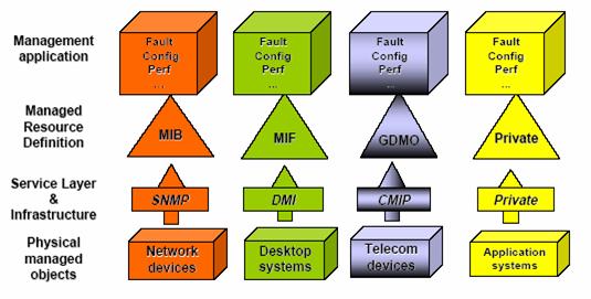
Figure 0‑5
Today's Enterprise Management Architecture
Figure 0‑5 shows the logical architecture of today’s enterprise
management. As discussed previously, multiple systems, protocols, standards,
platforms and approaches have been proposed and implemented which often deal
with a group of resources or functions and can create a challenge in providing
a broad and unified management perspective. This problem has been recognized
and solutions have been proposed within the communications and the computing
industries. A more recent web-based management
initiative focuses on unification of the various management systems rather than
their replacement. In addition to
providing interoperability, web-based management promises to provide a faster
way to implement and easier to use platform for management of entities through
use of common web languages and protocols such as XML and HTTP. This is to
facilitate information exchange between heterogeneous network management
entities/ platforms [Enns 03] by leveraging the wide availability of XML-based
parsing/ transformation tools.
Various approaches
to use of web technology with the purpose of unification have been proposed and
some are implemented. One approach, which is relatively easier to implement and
a good short-term solution, is to provide a web interface to the existing
enterprise management systems. For this approach, a web server, on the manager
platform, provides the link between the native manager and the web interface.
Clearly, this provides a uniform GUI for accessing management information, but
does not attempt to integrate the semantics of the underlying systems being
managed. As a result, some of the capabilities of management agent embedded
systems are not achieved. Figure 0‑6 provides the view of a web-based user interface to
enterprise management.
Figure
0‑6 A Web-based Interface to the Enterprise
Management System
4.
A more involved, but potentially better approach
in the long run, is specified by DMTF WBEM. The objective is not to replace any
existing management protocols/ solution, but rather to provide a set of
management and Internet-based standard technologies to unify the enterprise
management of large scale, heterogeneous distributed computing and
communication environments such as those found in IntelliGrid Architecture. As such, unification
and integration support of existing/ legacy enterprise management technologies
is a key theme of the DMTF WBEM.
Figure 0‑7 depicts the integrated management of a set of heterogeneous
technologies under the DMTF CIM/WBEM framework. The WBEM server receives and
processes WBEM operation requests issued by various management application
clients and performs semantic integration of the underlying systems. With the
help of technology-specific object providers, the WBEM converts a legacy
enterprise manager’s message from its native format to a DMTF CIM schema and on
the reverse side, determines which legacy enterprise manager a message belongs
to and converts that message to the format of that system and technologies. Any
new development of management objects may continue to be web-based and thus
allow for all the functionalities. However, the enterprise can continue to use
the existing network management systems. For communications between native DMTF
CIM-capable managed and/or managing systems, local DMTF CIM scheme expressed in
the Managed Object Format are first converted to XML documents or messages
based on the DMTF XML/CIM encoding scheme. The XML documents or messages are then
transported directly over HTTP protocol. To further align with the approach
taken by the recent Web-services initiatives, there are also ongoing activities
to define standards such that these XML messages/documents can be encapsulated
within SOAP envelopes before transported over HTTP. In the case where there are more than one
collaborating IntelliGrid Architecture enterprise management systems belonging to multiple
administration domains within a federation, they also communicate with each
other via this xmlCIM-over-HTTP or xmlCIM-over-SOAP-over-HTTP approach as shown in Figure 0‑8. The use of HTTP (or HTTPS) as the transport protocol
will facilitate the activities such as firewall traversal when communication
across multiple security perimeters is required.
A disadvantage of
embedded web-based management is the model complexity, requiring ability to
implement a web server within the agents and support DMTF CIM. Some devices may
not have sufficient computing resources to allow for such features. For these
devices, the doable approach is always to either use or implement a lite agent
functionality on the managed element and add the additional DMTF CIM/WBEM
functionalities on another element, the so-called Object provider, which will
convert the lite model to the DMTF CIM model. This has been shown in Figure 0‑7and Figure 0‑8.
Figure
0‑7 Web-based Enterprise
Management Architecture, which enables the Integration and Federation of
Heterogeneous IntelliGrid Architecture management technologies
Figure
0‑8 Collaborations amongst multiple Management
Systems

Figure
0‑9 The Internal Architecture of a WBEM Server
and its interactions with Management Application Clients and Managed
Devices/Systems
Figure 0‑9 illustrates the logical components of a WBEM server
and how it interacts with external components including management application
clients and managed systems. The protocol adaptors accept incoming requests
from management client applications through particular, possibly legacy
management protocols such as SNMP and translate these requests for the CIM
Object Manager (CIMOM). Under the DMTF CIM framework, Indicator Handlers are
used to support event-triggering mechanisms similar to SNMP traps. Converters
can be used to map CIM indicators to SNMP traps to support event notification
delivery to SNMP management clients. Note that, besides the usage shown in Figure 0‑9, the protocol adaptors can also be used to interface
with external object providers that do not support xmlCIM-over-HTTP.
The CIMOM is the
central component of a WBEM server. It operates as a service layer and
interface object providers to management clients. The CIMOM responds to
operations defined in the CIM operations specifications. It also handles object
providers registrations and forward requests to object providers and
repositories. It maintains CIM class/instance information and provides
read/write access to management information. It also supports the managed
object query as well as inter-object association traversal. The object provider is used to instrument
managed objects with one or more aspects of the CIM schema.
The DMTF CIM/WBEM
initiative has been successful in gathering strong supports from major software
and system vendors. Multiple commercial as well as open-source WBEM
implementations are available. These include the Microsoft Windows Management
Instrumentation (WMI), which is part of the Windows 2000 and XP
operating systems, the Solaris WBEM SDK by Sun Microsystems, the Pegasus
open-source WBEM implementation by the Open Group as well as the open-source
Standards Based Linux Instrumentation for Manageability (SBLIM) project
supported by IBM. On the networking front, the Storage
Network Industry Association (SNIA) also adopts the DMTF CIM/WBEM standards to
provider storage management functionality and has the support of major
networking vendors, such as Cisco, especially in the area of storage area
networks.
[Enns 03] R. Enns,
"XMLCONF Configuration Protocol", IETF Internet Draft
draft-enns-xmlconf-spec-00.txt, Feb. 2003
Enterprise Management And Power
Systems Integration
This section
encompasses the integration of a DMTF based Enterprise Management systems with
TC 57 based utility systems. It is
assumed that:
·
Enterprise Management already successfully
accomplished/integrated using existing Enterprise Management technology (treat
existing Enterprise Management apps as a black box).
·
Not trying to replace Enterprise Management -
only integrate it with power system management.
·
IntelliGrid Architecture integration only needed so that end-to-end
reliability applications can simultaneously analyze power and communication
systems.
·
Enterprise Management and utility system
security cannot be compromised.
With regard to
what data is exchanged, Enterprise Management/power system integration provides
another example where complementary semantic sets can be joined. Network device models tend to be
communication oriented. These models can
be seen as less rich and complementary from the point of view of utility power
system enterprise semantics.
Consequently, as described below, the primary strategy consists of
mapping IT resource communication parameters to utility operational model
elements to extend the later with the former.
With regard to how
data is exchanged, generally IntelliGrid Architecture based Enterprise Management integration
seeks to more fully common model enable device communication technology. Specifically, IntelliGrid Architecture based device integration
stresses the importance of enhancing IT resource communication models with
utility operational semantics. Instead
of integrating on the basis of a communication model, integration occurs via
the common use of a model enabled API such as 61970’s High Speed Data Access or
Generic Data Access. Note that both
communication protocols such as SNMP or CMIP as well as common model enabled
device communication API’s are generic in that they can be applied to
any device type do not hard code device specific semantics into the interface.
This deployment
scenario entails the creation of an Enterprise Integration Bus e.g. an integration
platform used to integrate the utility enterprise. The Enterprise Integration
Bus will support Enterprise Clients e.g. software components residing on the
Enterprise Integration Bus being used by an Enterprise system/network manager
and Enterprise Servers e.g. software components residing on the Enterprise
Integration Bus that carries out Enterprise client requests.
Integration Solution Details
·
Various enterprise management information models,
which include routing MIBs, are exposed to Enterprise Bus using IESCA Common
Services.
·
Enterprise Clients can browse/read/subscribe to
elements of the routing model as well as request updates to the model.
·
Note that typically updates would be performed by an
DMTF or SNMP or CMIP based manager application
·
Probably want to leverage the work done in the DMTF
Figure
0‑10 Using A Separate DMTF Integration Layer
In Figure 0‑10, the SNMP and CMIP network managers are adapted to
the operational integration bus via a DMTF server. Analysis applications focused on end-to-end
reliability of the power system consume power system and IT device operations
and management data. These new
applications can take into account previously unanalyzed variables and
comparisons. For example:
·
Telecom vs. power system load profiles. A utility’s ability to recover from a fault
that causes a large amount of event data and cascading alarms needs to be
managed. A utility may choose to
implement some sort of telecom load shedding during heavy power system loading.
Figure
0‑11 Using DMTF CIM Only On The Enterprise
Integration Layer
Figure 0‑11 illustrates the deployment scenario when only the
DMTF CIM are used as the integration technology.

Figure
0‑12 More Complete Integration
Figure 0‑12 illustrates the complete deployment scenario.
This section describes how a deployment of the CIM and GID
can be used to create a platform for legacy application integration. This
migration strategy is based on the deployment of adapters that convert legacy
ways of modeling and exchanging data to CIM and GID.

Figure 0‑13 Application
Integration Scenario
In this case, a control center application integration
project is considered. This development integrates the following applications:
·
Legacy EMS
·
New archive, state estimator, and power flow
·
Condition-based monitoring software
·
CIM-based power system modeling environment
·
Data Engineering Tool
This example
employed a CIM/GID-based message bus as illustrated in Figure 0‑13.
In this example, adapters are used to connect the
applications to the CIM/GID-based Message
Bus. These adapters server two purposes:
·
What data is exchanged
·
How data is exchanged
With regard to the internal representation of data within
applications or sets of tightly coupled applications, one can suggest that the
value to the utility of how an application natively models or exchanges data
internally is low. At the most, special analysis applications may only need to
browse the lineage of data (where it came from) for auditing/validation but not
details about native semantics. Consequently, application integration
provides a scenario where the semantics of each application may be assimilated
into the common model.
With regard to how data is exchanged, IntelliGrid Architecture
recommendations for application integration include the use of common model-enabled application integration
technology. Specifically, instead of
using a cross-industry publish/subscribe API
to link applications, IntelliGrid Architecture-based application integration employs a CIM-enabled
publish/subscribe API such as IEC61970
Generic Eventing and Subscription. Note
that both cross-industry and common model-enabled publish/subscribe API’s
are generic in that they can be applied to any application type and do not hard
code application specific semantics into the API.
In essence, applications and/or systems can continue to
use their internal data representation and exchange methodologies within their
own domains, but are required to map to the CIM APIs whenever data exchanges
involve external applications and/or systems.
This example illustrates the integration of transmission
related applications using the a message bus as shown in Figure 0‑14:

Figure 0‑14 Control Center Application
Integration
Figure 0‑15,
illustrates the specific GID interfaces
required to integrate the applications involved:
Figure 0‑15
Specific GID
Interfaces Used For Application Integration
One advantage of this approach is that it facilitates
incremental upgrading of the EMS and other
systems, primarily within utility operations centers. In this example, a new state estimator and
power flow application can be integrated with the legacy EMS
using a new CIM based data-engineering tool.
The data-engineering tool supplies CIM model information to the new
state estimator and power flow application.
The data-engineering tool also supplies a portion of the power system
model to the Measurement Data Server Adapter.
As discussed previously, an application uses the GID
to expose information within the context of the CIM. In this case, the Measurement Data Server
imports a small amount of the power model so that it can expose archive data
within a CIM context.
Keeping the shared model in sync across multiple
cooperating components is an important task.
The GID’s Generic Data Access Model
Change Events capabilities are used for this purpose. Figure 0‑16 illustrates this process:
Figure 0‑16 Data
Synchronization
The steps of such a Use Case are listed below:
1. The
User adds a new breaker to the EMS system’s
power system model, using the EMS model
server via the modeling server’s GUI.
2. The EMS GDA Server publishes a GDA
Model Change Event onto the Integration Bus.
3. The Model Change Event is
received by the GDA Client in the Asset Management System adapter. If there is a need to join EMS
and AMS data, a mapping from logical to
physical devices must be maintained. It
is possible that this mapping will be done in the AMS
or EMS adapter as illustrated in Figure 0‑17.
4. The
User is prompted to map new logical breaker to new or existing physical breaker
in asset model using the AMS Adapter Mapping
GUI
5. The
archive wrapper also receives a Model Change Event.
6. In
some cases, the Archive may have the ability to create a new archive point on
the basis of a pre-configured template.
If this is the case, then the Archive adapter can use this template and
the information in the Model Change Event to determine appropriate archive
configuration and add a new archive point automatically.
7. The
CIM model subset in archive is also automatically updated and archiving begins.
It is important to note that in order for the archive to present historical
data within a TC57 namespace, only a relatively small portion of the EMS
model must be maintained in the archive wrapper model manager.
Figure 0‑17
Keeping the Mapping From Assets To the Power System In Sync
This workflow example can also be applied to information
model changes such as the addition of a new attribute on a purchase order
class. While these changes are somewhat
more difficult to automate among systems, GDA Model Change Events have been
design specifically to address both instance data and information model
changes.
This scenario shows how applications can be connected
together with adapters that can be supplied off the shelf. The deployment of TC57 based technology can
lower cost significantly and thereby enable the creation of a single unified
integration architecture that heretofore would be too expensive.
Again, security, network/enterprise management, and data
management requirements need to be incorporated in this Use Case. Security
requirements are shown in IntelliGrid Architecture Intra-Control Center Environment, and
include:
·
Authorization Service for Access Control
·
Audit Service
·
Security Policy Service
·
User Profile and User Management
Network and enterprise management requirements, as also
shown in IntelliGrid Architecture Intra-Control Center Environment, can rely on readily
available standard technologies, such as the IETF’s Simple Network Management
Protocol (SNMP) and Web-Based Enterprise Management (WBEM).
Data management requirements, although greatly enhanced by
the available standards such as CIM and GDA, still need guidelines, additional
tools, and automated procedures that will allow actually implementation of
these concepts in the most efficacious manner.
As recovery of money spent on asset related operations is
not guaranteed, it is critical that asset related costs be managed wisely. Inevitably this leads to a need for analytic
applications including:
·
Asset Risk Management – what is the risk
associated with operating an asset
·
Calculation and optimization of asset lifecycle
costs
·
Calculation of asset availability – what is the
projected reliability of an asset
·
Asset replacement calculations – when to replace
a given asset
·
Asset maintenance and diagnosis – when to
optimally schedule asset maintenance
·
Asset performance – what is the value of an
asset
·
Capital plan management –future asset related
investment forecasting
·
Asset utilization analysis – how can assets be
more fully used
·
Financial analysis – how markets affect asset
valuation
This section describes how a deployment of the CIM and GID
can be used to create a platform for data warehousing. In this case, we
consider a complementary project to the application integration project with
apparently different goals. The project consists of substation asset data
analysis and integrates the following data:
o Asset/Equipment data
o Historical measurements
o Power system network models
Frequently, this type of data is in a database. With regard to what data is exchanged, one
can suggest that the value to the utility of how a database natively models is
low. Again, analysis applications may only need to browse the lineage of data
(where it came from) for auditing/validation but not detail about native
semantics. Consequently, data
integration provides a scenario where the semantics of each database may be
assimilated into the common model.
With regard to how data is exchanged, generally IntelliGrid Architecture
based data integration seeks to abstract data access technology from the
underlying storage technology.
Specifically, instead of using a cross industry data access API
such as ODBC to collect data, IntelliGrid Architecture based data integration employs a CIM
enabled such as IEC61970 Generic Data Access interfaces which is independent of
backend schemas and storage technology.
Note that both cross industry and common model enabled data access API’s
are generic in that they can be applied to any data type and do not hard code
applications specific semantics into the API. This architecture is illustrated in Figure 0‑18.
Figure 0‑18 CIM/GID
Based Data Warehouse With Message Bus
As described previously, it is important to note that GDA
includes the ability to notify clients when data has been updated in the
server. This functionality provides an important piece of the puzzle when
constructing an infrastructure that enables a single point of update for model
changes. For example, changes in an EMS
modeling server can be used to drive the configuration of an archive or
implement a synchronization routine with an asset management system.
The capability for the warehouse to be kept in sync via
GDA Model Change Events addresses a key interoperability issue. There is no widely used cross vendor/open
standard interface for the propagation of data changes into data warehouses.
Furthermore, reuse of these events to keep applications in sync for the
application integration can provide a significant savings when integrating the
utility.
By sharing a common CIM/GID
design framework, a message based application integration and data warehouse
solution can be built simultaneously. Fortunately this approach reuses shared
application wrappers to leverage the investment in each without requiring all
data to be copied to a data warehouse.
Separately, the cost of developing individual wrappers for data
warehousing and for application integration can be prohibitive. By exposing application wrappers directly via
CIM/GID without requiring an intervening
copy of all the data in a warehouse, flexibility is maximized while costs are
minimized.
Not necessarily copying all the data into a data warehouse
while still providing analysis application the appearance that all the data is
local is called “Virtual Data Warehousing”.
A Virtual Data Warehouse enables distributed access to disparate, remote
data sources with the ability to run federated queries across such
sources. To meet emerging business
requirements, data warehouses need to support lower data latency, reduce
storage of rarely used data, and allow access to remote structured and
unstructured data sources. The solution
to these demands lies in the federation aspect of information integration. Federation makes it possible to avoid
bringing all the data together by maintaining a logical view of a single
warehouse. That doesn’t mean that data
is never duplicated centrally, only that duplication is minimized and not
stored in a warehouse optimized for a particular asset analysis
application. The diagram below
illustrates the asset analysis project components.
Figure 0‑19
Asset Management Integration Example
In this diagram, a collection of databases including Asset
Management System (AMS), Outage Management
System (OMS), Work Management System (WMS),
and others are integrated using the GID
Server. The databases are aggregated
with power system modeling data supplied via the message bus. The databases are
tied directly to the Virtual Data Warehouse and not to the message bus for
performance. By avoiding the XML
messaging required by the message bus and only using the binary
interface-to-interface remote procedure calls, query performance of the
analysis applications is maximized. This
architecture highlights one of the advantages of using a transport neutral
interface such as GDA. In this
architecture, links are optimized to meet project goals while still enabling a
single standard off-the-shelf wrapper for applications. Application vendors can supply a single
standard wrapper for data warehousing and message based application
integration.
For example, an off the shelf Condition Based Monitoring
Application can connect directly into the CIM/GID
integration infrastructure using the GID
interfaces. Periodically, this
application examines current transformer loading and temperatures and after
running calculations, publishes results on to the bus. The Condition Based Monitoring Application
obtains required asset and power system information about equipment from the GID
server. Figure 0‑20 depicts the combined system.
Figure 0‑20 Combined Application Integration
And Data Integration Architecture
Figure
0‑21 illustrates the specific GID
interfaces required to integrate the applications and databases involved:
Figure 0‑21 GID
Interfaces Used to Integrate Applications and Data
Using CIM/GID application
vendors can “shrink wrap” a CIM/GID
compliant wrapper, the use of the CIM and GID
can lower the cost of integration to utilities by fostering
the market for off-the-shelf connectors supplied by application vendors or 3rd
parties. The time and money associated with data warehousing/application
integration wrapper development and maintenance is high. Typically, most money
spent on integration is spent on the wrappers. An off-the-shelf CIM/GID
wrapper can replace the custom-built “Extraction and Transformation” steps of
an ETL process. The availability of off-the-shelf CIM/GID
compliant wrappers is a key to lowering data warehouse construction costs very
significantly.
It is clear that utilities are under greater pressure to
simultaneously lower costs while at the same increase reliability and meet
shareholder expectations. As a
capital-intensive industry, attention naturally focuses on optimization of
assets. Effective and efficient use of
assets implies minimizing the total cost of ownership, i.e. minimizing the
purchase, installation, operation, and de-commission cost of assets. More fundamentally this means utilities must
more effectively manage:
·
Asset operations
·
Work management operations related to asset life
cycles
While “return on investment” (ROI) is a more commonly
known metric for the value of an investment, “return on assets” (ROA) more
accurately represents the value of asset related activity and
expenditures. ROA includes the actual
return from cost savings, increased asset utilization and productivity.
If ROA provides a concise metric, physical variations in,
as well as the geographic and organizational distribution of assets, make it
difficult to effectively manage assets or establish a uniform ROA calculation
method. In order to glean meaningful
information so that intelligent decisions and metrics can be derived from the
mass of data, analysis applications must be constructed. Thus, key to increasing ROA is analysis of
asset and work management operations. This paper discusses how a utility may
increase ROA via the deployment of a platform for asset related analysis
applications. This platform depends on
the use of standards and off-the-shelf EPRI applications. Specifically, the proposed solution describes
how international standards such as the EPRI/IEC Common Information Model (CIM)
and Generic Interface Definition (GID) can
be combined with off the shelf analysis applications to create a utility asset
analysis platform designed to maximize ROA.
The Energy Market Integration deployment scenario
describes how a utility might integrate Energy Market Transaction Servers with
utility operational systems, discussing the management of what data is
exchanged and how data is exchanged.
Energy markets are in a state of flux at this time, and
will most likely never result in a single market environment. Therefore, this
deployment scenario raises interesting questions about how much can or should
be standardized and how much must be left to changing circumstances. Although
these questions are true to some degree for all environments, the market
operations environment is particularly changeable.
Therefore, a uniform strategy for complete energy market
transaction service integration may not be possible. While it is clear that CME
based transaction servers can be integrated with the CIM with much difficulty,
ETSO and eTagging-based energy trading systems present the a more complex
deployment scenario from the point of view of managing semantic
heterogeneity. The reason is that unlike
internal application or data integration where data semantics can be
assimilated, the exact meaning of external energy trading may not be able to be
modified. That is, instead of creating adapters to transform the meaning of
data, energy market data must be reproduced more exactly for use in analysis
applications.
At the same time, energy market semantics do often
conflict with operational semantics. For
example, ETSO and NERC eTagging messaging models were developed independently
of the CIM. As a result, utilities may
not be able to achieve complete harmonization of market and operational
semantics. In this case, the best that
can be done is to precisely describe the differences rather than attempt to
change the different semantics.
Fortunately, as described in Section 3, RDF and OWL provide this
capability.
In practice RDF and OWL can be used to describe the
differences in information models in a precise computer digestible way. Since both ETSO and NERC have only defined a
set of message schemas and not unified information models, an information model
will need to be derived from the message schemas and then linked to the CIM/CME
classes and properties.
With regard to how data is exchanged, generally IntelliGrid Architecture-based
energy market server integration recommends the use of information model
technologies by market applications, including the use of electronically
available metadata of these information models so that their names, structures,
and differences are discoverable.
Specifically, instead of using a simple message passing API
to link applications, IntelliGrid Architecture-based application integration employs a complex
model-enabled message passing and data access API’s
such as IEC61970 Generic Eventing and Subscription and Generic Data
Access. Note that both cross-industry as
well as the model-enabled GID API’s
are generic in that they can be applied to any message type and do not hard
code message specific semantics into the API.
The diagram below depicts an ETSO ebXML or NERC
eTagging-based Energy Market network:
Figure 0‑22 ETSO
ebXML Or NERC eTagging Based Energy Market Server
Figure
0‑22 illustrates a utility energy market server
communicating with external trading partners via the Internet. In order to perform analysis, this energy
market data must be integrated with the rest of the utility enterprise (subject
to the market rules on authorized access).
Figure 0‑23 CME
Based Integrated Energy Market Systems
Figure
0‑23 illustrates a GID
based adapter that exposes a CME information
model. That is, the GID
has the capability to expose a namespace created in accordance with harmonized
CIM/CME models.
Figure 0‑24 ETSO
or eTagging Based Integrated Energy Market Systems
Figure
0‑24 illustrates a GID
based adapter that not only exposes an eTagging or ETSO information model but
also their exact semantic relationship to CIM/CME. That is, the GID
has the capability to not only expose a single information model, but also
multiple associated models as well as their inter relationship.
The question remains how well an analysis application can
perform over this semantic infrastructure.
In the case of a CME based market server, an analysis application can
perform calculations based on a set of known facts. In the case of an ETSO or eTagging based
market server, an analysis application can only perform calculations based on a
set of inferences. An inference is a
conclusion based on data that is not completely semantically uniform. Inferencing technology is a rapidly growing
field of study particularly as it applies to analysis and searching of Web
based resources. However, its use has yet
to be tested or proven in a more critical environment.
Again, security, network/enterprise management, and data
management requirements need to be incorporated in this Use Case. The security
requirements are shown in IntelliGrid Architecture RTO to Market Participants Environment are
much more extensive than for the previous Use Cases, and include:
·
Identity Establishment Service
·
Authorization Service for Access Control
·
Information Integrity Service
·
Confidentiality Service
·
Security Against Denial-of-Service Service
·
Inter-Domain Security Service
·
Non-repudiation Service
·
Security Assurance Service
·
Audit Service
·
Security Policy Service
·
Path and Routing Quality of Security
·
Firewall Transversal
·
Privacy Service
·
User Profile and User Management
·
Security Protocol mapping
·
Security Discovery
Network and enterprise management requirements, as also
shown in IntelliGrid Architecture RTO to Market Participants Environment, can rely on readily
available standard technologies, such as the IETF’s Simple Network Management
Protocol (SNMP) and Web-Based Enterprise Management (WBEM).
Data management requirements, as discussed in this Use
Case, is much more difficult than in the other Use Cases described in this
section, since common information models will most likely never be standardized
or implemented globally. Therefore, data management will have to rely much more
heavily on metadata discovery of the individual market information models, and
as much automated mapping as possible through the capabilities described above,
and through technologies such as RDF. Again, the need for guidelines, tools,
and automated methodologies is paramount to simplifying this complex task.
By sharing a common design framework, device, IT resource
management, application, data warehousing and energy trading integration
solutions can be built simultaneously. This approach reuses shared adapters to
leverage the investment in each. Separately, the cost of developing individual
adapters for all the integration tasks can be exorbitant. By exposing adapters
directly to the data analysis infrastructure without requiring an intervening
copy of all the data in an intermediate warehouse for analysis, flexibility is
maximized while costs are minimized.
It is said that
the average age of utility employees in the US is close to 50 years old. If one
combines the number of people that will retire over the next 5 to 10 years with
average utility power system engineer turnover, then it is a fairly safe
assumption that utilities need to carefully consider how system knowledge
continuity will be accomplished. This situation is compounded by the fact that
many utilities rely on systems that are customized for their particular
installation. For example, many utilities model a network differently even
though they may use the same modeling tool as their neighbor. A solution to
this problem can include agreement by utilities on standardized best practices.
Not only will agreement between utilities enlarge the knowledge pool so that
more effective integration and analysis can be accomplished, it will allow
utilities to wean themselves off customized solutions. The IEC and DMTF
standards can play an important role in the move towards non-biased
standardized solutions. The IntelliGrid Architecture compatible architecture presented here is
entirely based on standardized interfaces – free of political tugs-of-war and
vendor lock-in. Adoption of this architecture can help provide the continuity
that utilities need.
As stated above, the cost of application adapters required
to for an infrastructure for integration and analysis is the most significant
cost of deploying these technologies. An integration infrastructure based on
the IntelliGrid Architecture described here helps enable the availability of
off-the-shelf wrappers because application vendors and 3rd parties
can now reasonably expect that a IntelliGrid Architecture based solution developed for one
location could be used in others too. Furthermore these wrappers can be
deployed independently of what integration infrastructure the utility happens
to choose.
Standardization of
the IEC and DMTF technologies fosters interoperability of components for many
uses. One market that will likely be created as a result of this
standardization is the market for CIM/GID based analysis applications or
application add-ons. Today, every analysis applications or application add-on
must be extensively customized for every deployment. If an analysis or add-on
application supplier can assume the existence of the CIM and GID, then the
supplier can sell the same tool to different utilities with a minimal amount of
customization. Decreased development cost, together with competition, should
help drive down prices.
As discussed previously, traditional integration
techniques are limited by not providing the capability to discover information.
The approach proposed in this report facilitates inclusion of unstructured data
and avoids preordaining how data will be organized and analyzed. In doing so, this approach provides a
flexible approach for the future.
Fundamentally, integration with the using the IntelliGrid Architecture involves looking at the big picture. However, integration may
encompass data from a large or small set of applications. One does not need to
undertake a major project that requires many months to complete. The issue here
is the development of a long-term enterprise wide integration strategy so that
a small integration project does not become just another slightly larger island
of automation. Thinking at the enterprise level while integrating at the department
level minimizes risk and maximizes the chances for long-term success. Within
the context of a long-term plan, the IntelliGrid Architecture makes it possible to
tackle the problem of integration in a staged approach. Rather than having to
understand the relative mapping of all of the shared model for each application
that you may need in the future, IntelliGrid Architecture approach lets you start with a more focused approach
and expand the solution over time. For example, the GID can be used to provide
a CIM wrapper on existing data warehouses. You could start with one existing
data warehouse to enable the CIM based integration of only that specific data
warehouse. You can then increase the scope of the CIM and GID incrementally
until, eventually, all data in the various data marts, warehouses and
applications are all available via a unified CIM view. The inevitable
inconsistencies in meaning or content between existing databases and
applications can be gradually discovered and addressed as needed. In this
manner, the CIM and GID delivers incremental value with staged effort
throughout the process.
The sections above have described how the use of the IntelliGrid Architecture can allow components to connect and exchange information
automatically. However, there is one problem that cannot be resolved via
standards. The remaining problem is that every utility typically names objects
such as a breaker, substation, or any other resource in a non-uniform manner.
The ID used to refer to an individual breaker in one application will
frequently not match the name in a second application. To get the two
applications to exchange data, a name mapping must be created. This remains a
persistent road block to complete “plug and play”. However, creating a name mapping table does
not require custom programming and can frequently be partially automated by
using the name conventions that do exist within most applications.
The benefits of standardized data models and component
interfaces are clear. Utilities can significantly lower the cost of performing
integration by leveraging off-the-shelf components and wrappers from
application vendors or third parties. Furthermore, the standard models and the
standard interfaces provide a power system specific mechanism to more easily
deploy, configure and use an integration infrastructure. As a result, a utility
can achieve greater efficiencies and adaptability at a cost that is not
prohibitive.
This page intentionally left blank.