The Integrated Energy and Communication Systems Architecture
Volume III:
Models
EPRI Project Manager
Joe Hughes
Cosponsor
Electricity Innovation Institute Consortium for Electric Infrastructure to Support a Digital Society (CEIDS)
EPRI • 3412 Hillview Avenue, Palo Alto, California
94304 • PO Box 10412, Palo Alto, California 94303 • USA
800.313.3774 • 650.855.2121 • askepri@epri.com • www.epri.com
DISCLAIMER OF WARRANTIES AND LIMITATION OF LIABILITIES
THIS DOCUMENT WAS PREPARED BY THE ORGANIZATION(S) NAMED BELOW AS AN ACCOUNT OF WORK SPONSORED OR COSPONSORED BY THE ELECTRIC POWER RESEARCH INSTITUTE, INC. (EPRI). NEITHER EPRI, ANY MEMBER OF EPRI, ANY COSPONSOR, THE ORGANIZATION(S) BELOW, NOR ANY PERSON ACTING ON BEHALF OF ANY OF THEM:
(A) MAKES ANY WARRANTY OR REPRESENTATION WHATSOEVER, EXPRESS OR IMPLIED, (I) WITH RESPECT TO THE USE OF ANY INFORMATION, APPARATUS, METHOD, PROCESS, OR SIMILAR ITEM DISCLOSED IN THIS DOCUMENT, INCLUDING MERCHANTABILITY AND FITNESS FOR A PARTICULAR PURPOSE, OR (II) THAT SUCH USE DOES NOT INFRINGE ON OR INTERFERE WITH PRIVATELY OWNED RIGHTS, INCLUDING ANY PARTY'S INTELLECTUAL PROPERTY, OR (III) THAT THIS DOCUMENT IS SUITABLE TO ANY PARTICULAR USER'S CIRCUMSTANCE; OR
(B) ASSUMES RESPONSIBILITY FOR ANY DAMAGES OR OTHER LIABILITY WHATSOEVER (INCLUDING ANY CONSEQUENTIAL DAMAGES, EVEN IF EPRI OR ANY EPRI REPRESENTATIVE HAS BEEN ADVISED OF THE POSSIBILITY OF SUCH DAMAGES) RESULTING FROM YOUR SELECTION OR USE OF THIS DOCUMENT OR ANY INFORMATION, APPARATUS, METHOD, PROCESS, OR SIMILAR ITEM DISCLOSED IN THIS DOCUMENT.
ORGANIZATIONS THAT PREPARED THIS DOCUMENT
General Electric Company led by GE Global Research (Prime Contractor)
Significant
Contributions made by
EnerNex Corporation
Hypertek
Lucent Technologies (Partner)
Systems Integration Specialists Company, Inc.
Utility Consulting International (Partner)
ORDERING INFORMATION
Requests for copies of this report should be directed to EPRI Orders and Conferences, 1355 Willow Way, Suite 278, Concord, CA 94520. Toll-free number: 800.313.3774, press 2, or internally x5379; voice: 925.609.9169; fax: 925.609.1310.
Electric Power Research Institute and EPRI are registered service marks of the Electric Power Research Institute, Inc. EPRI. ELECTRIFY THE WORLD is a service mark of the Electric Power Research Institute, Inc. All other trademarks are the property of their respective owners.
Copyright © 2002, 2003, 2004 Electric Power Research Institute, Inc. All rights reserved.
This document describes research sponsored by EPRI and Electricity Innovation Institute.
The publication is a corporate document that should be cited in the literature in the following manner:
THE INTEGRATED ENERGY AND COMMUNICATION SYSTEMS ARCHITECTURE, EPRI, Palo Alto, CA and Electricity Innovation Institute, Palo Alto, CA: 2003 {Product ID Number}.
Executive summary
Introduction
The breadth of the Integrated Energy and Communications Systems Architecture (IntelliGrid Architecture) is enormous – spanning from the complex interactions of market trading to real time, self-healing power system control to the emerging market of home automation – all needing to be linked through a robust, integrated communication system. To accomplish this, the power system will need to be supported by an equally robust and self-healing communications and automation infrastructure; however, building such large-scale distributed information processing systems is not easy. It is a very complex task to design an architecture that reconciles requirements of an industry with the complexities of distributed processing systems.
There are limits to human ability to understand such complexity and to solve large sets of system equations. The problem must be broken down or divided into a series of smaller problems that can be solved. Modeling is one of the proven and well-accepted engineering techniques that simplify the system, so that we can better understand the system being developing. System simplification is achieved through the introduction of levels of abstraction, which allow the modeler to focus on one particular aspect of the system at a time. [1]
Scope and Purpose
The scope and purpose of Volume III of IntelliGrid Architecture is to outline the technical details behind the development of IntelliGrid Architecture model. This volume will present to the reader the following topics:
· Basic modeling concepts used to capture the industry requirements.
· Guide to Notation used to express the modeling concepts.
· Definition of basic rules used to document the architecture.
· Guide to understanding the structure and organization of the content within the model.
Key Findings
The IntelliGrid Architecture model captures the collective industry requirements as defined by project stakeholders (see list of contributing stakeholders in Volume II Appendix B). These requirements have been collected using the process outlined in the stakeholder engagement plan (Volume II Appendix A) and distilled into the abstract structural and behavioral modeling elements. Information on the architectural analysis processes may be found in Volume IV. Future and follow-on projects may serve to enhance the richness and completeness of these requirements and supporting modeling elements.
Recommendations
Architecture must evolve over time to reflect the new
business needs and technological approaches.
It is the recommendation of IntelliGrid Architecture team that the overall enterprise
architecture and intermediate work product developed during IntelliGrid Architecture project
(processes, templates, tools, and recommendations) serve as the basis for
future projects. The IntelliGrid Architecture team has made significant achievements in the
application of standards based systems engineering methodologies towards the
definition of the Enterprise Architecture. This architecture will provide
significant benefit to improved system management in support of business
requirements, at lower cost, faster time-to-market, and increased technical
ability. That is, the benefits of the enterprise architecture can be summed up
using three words: [2]
· Better. Working towards a common business vision and common technical infrastructure.
· Faster. Significant issues have been previously thought out.
· Cheaper. Don’t reinvent the wheel every time a new system is built.
Where the Enterprise architecture models act as bridges between the business
and the technical sides of the organization. A model that focuses primarily on
business issues, or on technical issues, will not meet the real-world
needs. If business stakeholders do not
see concepts that they can understand, and mappings of those concepts to
technical ideas that they may not immediately comprehend, they will soon
abandon the enterprise architecture efforts.
Similarly technical staff will also abandon an enterprise architecture
that focuses solely on the business. The
architecture needs to find the modeling “sweet spot” that meets everyone’s
needs.
Contents
1.3 Organization and Special
Features
2 Use of RM-ODP and UML mapping
2.1 Reference Model for Open
Distributed Processing
3 Architectural analysis process
Step 1 - Identification
of Functions
Step 3 – Requirements
Capture, Use Cases
Step 4 - Analyze, Normalize and Refine
Step 6 - Identify
Abstractions, Common Services
Step 7 - Identify
Technologies/Standard Activities/Best Practices
4.2 IntelliGrid Architecture Model
4.2.1 Navigating IntelliGrid Architecture
Model
4.2.3 IntelliGrid Architecture UML Profile
4.2.7 PIM [Platform
Independent Model]
Appendix A - Electronic Attachments.............................................. A-1
Appendix B - UML/RM-ODP Mapping of
Concepts.......................... B-1
Figures and Tables
Figure 1: Descriptions of
the RM-ODP Standards
Table 1 Description of the
RM-ODP Standards
Figure 2: Architecture
Development Process
Figure 3: Migration of
Requirements to the Model
Figure 4: Analysis of
Filled Domain Templates and the UML Model
Table 2 Domain Template
Quality Checks
Figure 5: IntelliGrid Architecture Placemat
Figure 6: IntelliGrid Architecture Model –
Key Concepts
Figure 7:Top level package
structure of IntelliGrid Architecture Model
Figure 8: IntelliGrid Architecture Domains
Figure 9: IntelliGrid Architecture Viewpoints
Folder
Figure 10: IntelliGrid Architecture
Environments
Figure 11: IntelliGrid Architecture
Architectural Issues as Tagged Value Definitions
Figure 12: IntelliGrid Architecture
Stereotypes
Figure 14: Example Class
Operations (Contract)
Figure 18: Example
Community Membership
Figure 19: Contract
Governing Actors
Figure 20: Activity
Diagram (part-of)
Figure 21: Collaboration
Diagram (part-of)
This
page intentionally left blank.
Overview
This volume describes the development process for the overall IntelliGrid Architecture. It includes a definition of the notation, the architectural development process and the organization of IntelliGrid Architecture model. This section does not to provide the reader with any rationalization of the analysis. The results of the team’s analysis are found in Volume IV of IntelliGrid Architecture deliverable.
Purpose
The purpose of this volume is to outline the technical details behind the development of IntelliGrid Architecture model. It defines the organization and structure of the IntelliGrid Architecture. It describes a set of basic modeling concepts and rules upon which IntelliGrid Architecture is built. The team leverages Reference Model for Open Distributed Processing (RM-ODP) – an international standard for open system architecture development, to provide the underpinning concepts and rules. The team applies the Unified Modeling Language (UML) to map RM-ODP onto a standard notation.
Audience
This volume is of interest for anyone attempting to understand, implement, utilize or contribute to IntelliGrid Architecture. This volume details how IntelliGrid Architecture model is constructed and provides the reader with a set of governing rules that ensure architectural consistency.
This volume does assume basic working knowledge of architectures and architectural concepts defined by the Reference Model for Open Distributed Processing (RM-ODP) as well as familiarity with the Unified Modeling Language (UML) – the standardized notation used document these concepts.
Organization and Special Features
Section 1: Overview
This section.
Section 2: Use of RM-ODP and UML Mapping.
Section 2 provides a key to the notational constructs representing the various RM-ODP modeling concepts used to develop the overall IntelliGrid Architecture. RM-ODP is an international standard (ISO/IEC 10746) for architectural development; however, RM-ODP does not define a notation. The Unified Modeling Language (UML) provides the standardized notation that graphically documents the systems and components of the architecture. Together, using RM-ODP to provide the architectural guidance and UML to provide the standardized notation, the IntelliGrid Architecture can be developed and precisely documented.
Section 3:
Architectural Analysis Process.
Section 3 provides a description of the process the team used to develop the overall IntelliGrid Architecture. This includes the steps the team arrived at for the overall architectural analysis
Section 4: Structure
of UML Model.
Section 4 provides a guided overview to the organization of IntelliGrid Architecture model, providing the reader with an understanding of where to find different concepts within the Model. The model is defined using UML as the standardized notation and is built upon the five orthogonal viewpoints defined by ODP.
Appendix A: Electronic Attachments
IntelliGrid Architecture Navigable Model
The UML Model contains an exact specification of all the components modeled in IntelliGrid Architecture, however, without adequate background in UML and ODP, this information can be difficult to navigate and understand. To make the results more understandable and useful to a wider audience, information is extracted from the UML model – and presented in a web-navigable (hypertext) report. This report ties together key concepts contained within the model without sacrificing the rigor and standardized notation used to document the model. The results can then be presented in a human-friendly manner.
IntelliGrid Architecture UML Model
The UML Model contains an exact specification of all the components modeled in IntelliGrid Architecture. The MagicDrawÔ UMLCASE Tool is required to utilize the information in this format.
Tools
In order to support manipulation of such a large model, the team also developed extensions (plugins) to the UML tool. These tools are provided in both binary and source form.
Appendix B: IntelliGrid Architecture UML Mapping of Concepts
Defined in the Reference Model of Open Distributed Processing
The key RM-ODP concepts used in IntelliGrid Architecture are mapped to UML. Appendix B summarizes the mapping in an alphabetic order. It serves as a cheat sheet for the reader to searching for how the RM-ODP concepts are utilized in IntelliGrid Architecture.
For More Information
The most current information on RM-ODP and UML standardized notation, including their formal specifications, may be found at www.omg.org.
Use of RM-ODP and UML mapping
The charter of IntelliGrid Architecture is to use a rigorous, standard modeling methodology. The selected methodology is the International Organization for Standardization (ISO 10742) Reference Model for Open Distributed Processing (RM-ODP). RM-ODP, ITU-T Rec. X.901 | ISO/IEC 10746-1 to ITU-T Rec. X.904 | ISO/IEC 10746-4 [5][6][7][8], provides a framework to support the development of standards that will support distributed processing in heterogeneous environments. It is based, as far as possible, on the use of formal description techniques for specification of the architecture. In support of the generic design goals, it facilitates specifying integration architecture with the following properties: openness, flexibility, modularity, federation, manageability, and provisions for quality of service, security and transparency[3]. Thus, the team has selected RM-ODP as the enterprise architecture framework for IntelliGrid Architecture.
In the section, we describe RM-ODP and the modeling concepts used in IntelliGrid Architecture. The team extended the RM-ODP by including domain specific concepts such as common services to represent generic interfaces and functions that the power system distributed computing system will use.
RM-ODP is silent on the notation to be used for rendering architectures. Thus, the team selected the Unified Modeling Language (UML) [4] tool to provide most of the notation support capabilities for RM-ODP. The mapping between RM-ODP concepts and UML constructs will be discussed further below.
Reference Model for Open Distributed Processing
RM-ODP uses an object modeling approach to describe distributed systems. Two structuring approaches are used to simplify the problems of design in large complex systems: five 'viewpoints' provide different ways of describing the system; and eight 'transparencies' identify specific problems unique to distributed systems which distributed system standards may wish to address. Each viewpoint is associated with a language, which can be used to describe systems from that viewpoint.
Figure 1: Descriptions of the RM-ODP Standards
|
Part |
Name |
ITU
Standard / |
Description |
|
1 |
Overview |
ITU-T Rec.
X.901 / |
The Overview contains justification and explanation of key concepts. The overview begins with the initial list of enterprise activities that facilitate the stakeholder engagement process. Utilizing a rigorous template (Domain Template), IntelliGrid Architecture interacts with stakeholders to elaborate a set of use cases and architectural requirements, which contribute to the key concepts, interfaces, actors and constraints used to define the architecture. |
|
2 |
Foundation |
ITU-T Rec.
X.902 / |
The Foundation contains the definition of concepts. The UML modeling constructs applied to RM-ODP provides the foundation for the modeling activity. The modeling tool, in conjunction with the RM-ODP to UML mappings, provides the foundation for the modeling activity. The MagicDrawÔ tool also provides the team with the capability to cooperate on the development of the model. |
|
3 |
Architecture |
ITU-T Rec.
X.903 / |
The Architecture contains the specification of the required characteristics that qualify distributed processing as open. As the stakeholder inputs are analyzed, the orthogonal viewpoints help to focus the team on details that enable the distributed processing. |
|
4 |
Architectural Semantics |
ITU-T Rec.
X.904 / |
The Architectural Semantics contains a formalization of the modeling concepts. Formal notation can be used in conjunction with the modeling tool to specify the constraints and semantics of the architecture. |
Table 1 Description of the RM-ODP Standards
The above table presents the structure of RM-ODP standard as well as its viewpoints, namely enterprise, information, computational, engineering and technology viewpoints.
Enterprise Viewpoint
The enterprise viewpoint represents the business model and the business requirements. This view should be understandable by all stakeholders in the business environment. It is the viewpoint used to communicate the business needs to the architecture. The viewpoint is concerned with purpose, scope, and policies of the enterprise. The enterprise view of IntelliGrid Architecture provides the business objectives, roles, policies and the environment with which the enterprise interacts. It covers the role of the systems in the business as well as the human user roles and business policies.
The key concepts we used in the enterprise viewpoint are:
Purpose and objectives – In RM-ODP, “purpose and objectives” concept is used to capture the reason for the system. It defines a set of objects formed to meet an objective, their activities, and processes in which the system participates. For example, the purpose and objective of the ‘Base RTP Calculation’ function is defined as:
“To develop tables of load versus price for each power system node and for each settlement period. These tables are the Base RTP data. The purpose of this computation is to accurately forecast the cost of providing energy during the period.”
Domain – In RM-ODP, a domain is a set of objects with a characterizing relationship, and with a control object that may be part of the domain or outside it [3]. In IntelliGrid Architecture, a domain is a grouping of enterprise activities that fall into a natural boundary of the power system operations. IntelliGrid Architecture partitions the entire architecture into five domains, namely, Market Operations, Primary Generation, Transmission Operations, Distribution Operations, and Distributed Resources.
Activity/Enterprise Activity – In RM-ODP, an activity is an ordered set of actions. In IntelliGrid Architecture, we use this concept as well as the term enterprise activity as a specific power system operation. For example, in the Base RTP Calculation, “Load Forecasting” is an enterprise activity. This activity is an ordered set of actions, which result in providing accurate estimates of load at various points in the settlement intervals.
Community – As defined in RM-ODP [3], a configuration of interacting objects whose purpose is to fulfill an objective according to a contract defining how the objective can be met. Market Operators and Energy Service Providers are examples of communities.
Actor/Artifact – An actor is an enterprise object, a person or a system, which plays a role in the enterprise view. When the actor is a piece of data/information, we use the term Artifact. Load Forecasting Function and Market Interface Server are examples of actors in the Market Operators’ community.
Role – A unique identifier that characterizes some behavior [3]. A role defines the behavior of the objects within the community.
Scope – The set of roles, which define a business, is the scope of that business.
Contract – As defined in RM-ODP [3], a specified agreement to some behavior common to a configuration of objects, that tells the environment what to expect.
Policy – RM-ODP defines contract [3] as a set of obligation, prohibition, or permission rules that either constrain or enable actions, as related to the purpose. A contract contains zero or more policies.
Information Viewpoint
The information viewpoint is concerned with the semantics of information and information processing. The information specification of IntelliGrid Architecture is a model of the information that it holds and of the changes to that information. The information viewpoint is similar to object models such as the IEC61970 Common Information Model (CIM) and Utility Communications Architecture’s (UCAÒ) Generic Object Model for Substation and Feeder Equipment (GOMSFE).
The key concepts we used in the information viewpoint are:
Information
Objects – The set of objects
in the information viewpoint. This set of objects includes the information
objects used in interactions as well as the objects carried from the enterprise
viewpoint actors and artifacts. For example, in Base RTP Calculation, Marginal Energy Cost is
the information object that represents the table of marginal energy
costs for the power system.
Association – Defines the relationship between the information objects. For example the association between the Market Operator and Energy Service Provider that is providing regular and continuous RTP base rates for ESP to calculate RTP customer rates.
Contract – As defined in the enterprise
viewpoint. For example in BaseRTP Calculation a contract is the RTP Tariffs which
dictates the conditions and limits and
tariff of the RTP contract that can be entered with customer.
Policy – As defined in the
enterprise viewpoint. An example is a security policy, which must be
established and used to address all security, needs
at the appropriate/contracted levels.
Computational Viewpoint
The computational viewpoint is concerned with the interaction patterns between the components (services) of IntelliGrid Architecture, described through their interfaces. A computational specification of a service is a model of the service interfaces seen from a client, and the potential set of other services required by that service. The computational model defines types of interfaces such as request/reply or publish/subscribe or whether an interface is designed for exchange of real time or historical data or both. Example interfaces include Application Programming Interfaces (API’s) such as Control Center API’s (CCAPI) Generic Interface Definition and UCAÒ’s device oriented Common Application Service Model (CASM) services.
The key concepts we used in the enterprise viewpoint are:
Computational Objects/Components – Objects that interact at interfaces. The set of computational objects were carried from those defined in enterprise and information viewpoints. For example, in BaseRTP Calculation Base RTP Calculator and Market Interface Server are objects.
Interactions – RM-ODP defines [3] interaction as an action that involves one or more objects and their environment(s) at an interface; set of services that are offered across a single interface, and are linked to another object with a binding.
Interface – According to RM-ODP, an interface defines the behavior of an object at a subset of the object’s interactions constrained by the circumstances for when they occur. An operation interface is a type of interface where the interactions are of type interrogation (request-response) or announcement (publish-subscribe). For example, in BaseRTP Calculation Base RTP Calculator interacts with Market Interface Server, posting RTP tables on Market Interface Server for ESPs to access/download, through an interface defined by the set operations.
Binding – RM-ODP defines binding as a contract between two or more object interfaces that is the result of an agreed upon behavior. Bindings support the interfaces and provide the environment where the interactions can be executed.
QoS - Various metrics of Quality of Service, such as bandwidth, delay and reliability requirements have been used in IntelliGrid Architecture computational viewpoint.
Engineering Viewpoint
The engineering viewpoint is concerned with the design of distributed systems. Since IntelliGrid Architecture is an architecture framework, independent of implementation and outside the scope of the current charter of IntelliGrid Architecture. Future works, based on IECA man contribute to the definition of the engineering viewpoint.
Technology Viewpoint
The technology viewpoint is concerned with the provision of an underlying infrastructure. It focuses on the technologies and the products for implementation. Even though IntelliGrid Architecture is an architecture framework, the team felt that there are technology considerations that can be made independent of exact implementation. The technology viewpoint of IntelliGrid Architecture discusses the technologies, best practices, and standard activities that can support the environments of IntelliGrid Architecture. It includes the various alternatives, and identifies technological gaps.
RM-ODP Rules
In order to maintain consistency among these viewpoints, RM-ODP puts forth a set of basic rules, object model rules, structuring and specification rules, and conformance rules. The structuring and specification rules include organization, properties, naming, behavior, as well as abstraction, refinement, and composition concepts, which provide unique capabilities to architect a system. The object model rules provide the powerful concepts of multiple types that an object can assume, and multiple interfaces that an object can offer. The OMG and others have accepted these rules and concepts for specifying a complete characterization of the enterprise.
By design, RM-ODP does not define a specific notation for rendering architectures. This choice is left to the architects and as such the team has not been able to identify suitable commercial tools that directly support its concepts. However, the team has selected OMG’s Unified Modeling Language (UML) for the architecture specification and rendering.
RM-ODP to UML Mappings
The team developed a cross reference for mapping RM-ODP concepts into UML for the purposes of describing IntelliGrid Architecture. A mapping between RM-ODP and UML is needed since RM-ODP represents powerful modeling concepts and provides an abstract framework for defining distributed systems, however, it does not define the notation for describing its constructs. On the other hand, UML provides a rich notational syntax, but lacks the higher order constructs needed describe a distributed architecture. By analogy, we could say that UML provides a rich vocabulary and alphabet, but does not have the elements to describe a literary work.
Even though UML provides a rich notational syntax, some of the RM-ODP constructs do not have a direct correspondence in UML. While RM-ODP is gaining in popularity, there are relatively few comprehensive references illustrating a complex architecture and the references that do exist, use a different notation for the same RM-ODP constructs. As IntelliGrid Architecture project began, it became obvious that the team needed to standardize on the notation of certain RM-ODP constructs in order to ensure consistency in the design.
Adopting UML as the notation used to describe RM-ODP constructs also exploits the ability of software engineering tools to test the operation of the architectural components and to observe the “consequences” of the design choices. Decisions to use certain notational constructs will affect the ability to enforce design consistency in the engineering tools. For complex systems it is absolutely critical to choose the representation that best exploits the consistency and validation checks available in the modeling tool.
As a result of our research into the mapping of RM-ODP to UML, it is clear that others are struggling with these notational constructs of RM-ODP and have differing opinions on how to best map RM-ODP to UML. For the mapping between RM-ODP viewpoints to UML, we started from the approximate mapping selected by [17] and created IntelliGrid Architecture specific mapping with domain specific considerations. The details of the mappings are described in Section 4 as well as in Appendix B of this document.
Architectural analysis process
In accordance with the utility industry specifics, and the standard bodies common architecture development process, the team put together an RM-ODP-based architecture development methodology along with the appropriate template to collect requirements based on RM-ODP components. The team’s architecture development process is shown in Figure 2: Architecture Development Process.

Figure 2: Architecture Development Process
Step 1 - Identification of Functions
In step 1, the team identified a set of power system functions and operations, which expose architecturally significant requirements. This step was discussed in details in Volume II. Completion of this step provided the team with a starting set of functions to investigate and use to capture the requirements. Amongst other considerations, the significant criteria used in selection of Functions are listed below.
Functions that span across multiple power systems business domains – Cross-domain Use Cases expose the need for common, horizontal services in the architecture. For example, Real Time Pricing (RTP) applications span across Energy Service Provider, Market Operations, Distributed Resources, and Consumers domains. Significant inter-domain interactions and coordination amongst the entities are needed to assure proper operations. This is a collaborative problem solving application that requires involvement of different organizations and thus exposes the need for appropriate architectural support. Examples of requirements include assuring end-end network management capabilities to meet Quality of Service (QoS) and reliability requirements, development and enforcement of cross-organizational security policies to meet security requirements, and finally inter-domain coordination of activities to access timely data.
Functions that are critical to the operations of the self-healing grid – Such Use Cases expose the requirements and the resulting architectural needed to support the self-healing grid. For example, inclusion of Advanced Distribution Automation (ADA) and Wide Area Measurement and Control (WAMAC) provide to the architecture the requirements of self-healing functions. They emphasize the need for real-time response, proactive measurement and test, secure operations environment and availability of uncorrupted critical data for decision-making.
Functions that expose the requirements for new and emerging services - These Use Cases provide the architecture with what future and emerging services are expected to look like and the type of support needed for the underlying communications architecture. Examples of new and emerging services are shown in the RTP case, in areas such as home automation, trading services and advanced load balancing. Also, Use Cases such as ADA and WAMAC expose the requirements of the real-time sensitive, and computationally intensive components.
Step 2 – Domain Template
In parallel with Step 1, in Step 2, the team developed a domain template to collect the functional and non-functional requirements with emphasis on architecturally significant requirements of the Use Cases. The template is heavily based on RM-ODP concepts and views. Yet, the template was strategically designed to be devoid of technical jargon so that the domain expert could express concepts in natural language and his/her own nomenclature. The template has been discussed in more details in Volume II Appendix C. The importance of the domain template was its ability to provide a uniform framework for capturing the requirements, and its ability to simplify the move from requirements capture to analysis through use of RM-ODP-like concepts.
Step 3 – Requirements Capture, Use Cases
Finally, in Step 3 the requirements for the Use Cases were captured through frequent interactions with stakeholders and other domain experts, as well as use of existing documents and research results. The IntelliGrid Architecture team, in order to capture the detailed functional and non-functional system requirements, consulted multiple information sources. Figure 3 illustrates the various sources and the way the requirements were transferred into the UML model. In most cases, the information was input into the UML model by a JavaÔ program interfacing with MagicDrawÔ API. The program reads the well-structured completed domain template, builds the UML constructs and diagrams, and populates the UML specifications. More details on this program is given in Volume III Appendix A
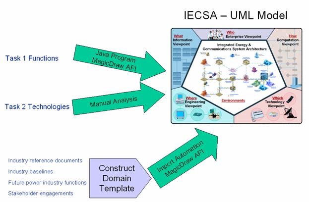
Figure 3: Migration of Requirements to the Model
The sources of information/requirements include:
·
Task
1 Functions – The team used information on approximately 400 present and future
utility functions that were identified during Phase 1 of IntelliGrid Architecture project.
These functions collectively expose the requirements for IntelliGrid Architecture. These requirements
were input into IntelliGrid Architecture UML model automatically from the Excel sheet, using a
JavaÔ program in conjunction with the
MagicDrawÔ API. For a complete list of these
functions, see Volume II Appendix F.
·
Task
2 Technologies – The results of the Task2 Existing Technologies &
Standards investigation are incorporated into the models manually where
appropriate. These technologies are included where the specific functional and
non-functional requirements need to be met. Some of the technologies are
further described and specific recommendations are made in Volume IV, Section
3.
·
Industry
reference documents – The industry reference documents were used to enhance and
complement the requirements captured in the domain templates. As a result of
automatic porting of the requirements, the industry reference information was
also included into the model. IEC TC57 documents are examples of such
documents. Additional documents are listed in Volume II Appendix A.
·
Industry
baselines – Requirements for industry baseline functions were captured through
the domain template and input into the model automatically thorough the JavaÔ API to MagicDrawÔ. An example of a baseline function is Emergency
Operations Baseline, part of the Wide
Area Measurement and Control Use
Case.
·
Future
power industry functions – This information was obtained by IntelliGrid Architecture team’s
research and stakeholder involvement. Again, the information is included into
the model through construction of a domain template for each such functions and
automatic porting of the templates into the model. ADA in its entire form is an example of a
future power system function.
·
Stakeholder
engagements – The IntelliGrid Architecture team hosted numerous meetings with stakeholders that
resulted in the elaboration of the contents of the filled domain templates and
incorporation of significant requirements. The stakeholder engagement strategy
is outlined in Volume II Appendix A and the list of stakeholders engaged can be
found in Volume II Appendix B.
Step 4 - Analyze, Normalize and Refine
In Step 4, the information in the filled templates and the model were analyzed, through multiple iterations and communications with the stakeholders and other experts. The UML model that was initially populated by the automated routine was refined to include more specific information and constructs. As a result of the analysis, the filled templates and the UML model were modified to assure consistency and accuracy within the model and across to the other requirements. Figure 4 illustrates that the analysis process involves the nexus between textual tools (MSWord and Excel) and UML tools. The analysis is shown as a black box in the figure to suggest only that a rational process is required and that the results (rendered architecture) flow from the inputs (Raw sources & Domain Templates). There was no predisposition as to where and how the analysis was conducted. However, the process chosen is described herein.

Figure 4: Analysis of Filled Domain Templates and the UML Model
The analysis and refinement resulted in creation of normalized source material so that common actors, data elements, functions and interfaces that are the same but have slightly different names can be adjusted to a single representation wherever it is used. The tools of analysis preserved the relationship between normalized components and the original sources.
As a result of some preliminary analysis, the team decided to define the notion of environment for the purpose of giving a subset of requirements a context, or environment, within which they need to be satisfied. This was essential for the development of solutions since solutions depend on the environments within which they need to be applied. For example, a requirement of 5-second response time may have a different solution whether the requirement is for a function within a substation environment with a tightly managed Intranet or within a consumer eCommerce environment with public Internet as the means of communication. More details on environment can be found in Volume IV Appendix E.
The normalization process was accomplished via the following steps:
1) Import Domain Template into UML tool using custom import tool
2) Observe anomalies in imported model due to inconsistencies in naming usage.
3) Correct Domain Template in text editor, with help and input from the stakeholders as necessary, and repeat step 2 until anomalies are resolved
4) Import all domain templates into model
5) Use custom report generator tool to produce a summary of all nomenclature used for actors, information items, etc.
6) Find terms used in different domain templates that represent the same items except from the perspective of a different author
7) Resolve the naming overlaps and conflicts in individual domain templates
8) Import again for final time – resulting in normalized domain templates and model elements
The following table summarizes Domain Template quality attributes to be ensured prior to completion:
Table 2 Domain Template Quality Checks
|
Make sure that the narrative is self contained and that everything mentioned in the narrative appears in the remaining sections. Ensure that the nomenclature used in the remaining sections matches that used in the narrative. |
|
If this document is related to other documents done by the author or others, the narrative should begin with a summary of this relationship. Introductory material that is taken from the other documents to allow this document to have a context should be clearly identified as such so that its description is not expected in the rest of the template. |
|
Make sure the names of the actors as listed in Section 1.5 are consistently used throughout the document (specifically in Sections 1.8 and 2.1 of the template). Note that the automated routine is not a spell checker, nor is it a reasoning engine to discover what the author really meant. Check also for common capitalization, small differences in usage, abbreviations vs. whole words (i.e. ESP and elsewhere Energy Service Provider). Note: You may denote a list of actors using comma as a separating character. This is important since the use of different terms for the same entity – will result in the creation of two separate modeling elements – where only one should exist. |
|
In Section 1.8 of the use case, the policies belonging to a contract should immediately follow that contract in a table. Thus, for any contract in the contract table, there could be a set of zero or more policies that follow it immediately. Check with the domain expert to make sure that all the contract/policy pairing is observed. A common mistake is to put all contracts first in a table, follow by all policies in the next table. In such a case, the policies will all be placed part of the last contract on the contract table. |
|
Delete empty rows and empty tables. |
|
In the sequence tables of Section 2.1. Make sure that there are primary, information producer and information receiver actors and further they are all valid actors of 1.5. |
|
In the sequence tables of Section 2.1. The primary actor is either an information producer, or receiver. By definition a primary actor is one that initiates the activity. |
|
Make sure there is a “Domain Template Architectural Issues” spreadsheet in Section 2.2. is correctly filled in. Ensure that the steps in the columns are the same as the row identifiers in the word section. Also, these labels must be in row 4 of the spreadsheet. |
|
For each diagram – fix diagram layout. Ensure that the terminology in the diagram match up with the terminology in the narrative and body of the filled in template. |
Step 5 - Develop Viewpoints
Step 5 includes the task of modifying the UML model and rendering the results of the analysis in parallel with step 4. Throughout the analysis phase, the automatically generated diagrams and model elements were modified to reflect the normalized, and refined model components that express the RM-ODP viewpoints. The UML model can be navigated use a web browser – see Volume III – Appendix A.
Step 6 - Identify Abstractions, Common Services
In Step 6, the team massaged and further analyzed the resulting model to separate common elements and interfaces that isolate domain specific functions from horizontal services that are elements of the emerging “architecture” and would support the domain functions. The team further investigated into the requirements and refined the model to extract and add the common services that satisfy the requirements in whole or in part, to align well with industry defined common services and abstractions. Example of a common interface is one where data is provided accurately and timely on a specific platform to be accessed by the application. Examples of a common service is the service to provide a transport of a specified BW, or one that provides reliable communications through performance monitoring and timely alarm processing. As these services were identified, they were incorporated into the model. The common interfaces and services are further elaborated and listed in Volume IV – Appendix D.
Step 7 - Identify Technologies/Standard Activities/Best Practices
Following analysis and identification of the common interfaces and services, the team investigated the various technologies/best practices/standard activities that provide solutions for the constructs and meet the requirements of the architecture, the interface, services and functions. The team followed a non-judgmental initial approach by considering all mature, new, or emerging technologies, as well as the activities of the standard bodies and the best of common practices. The team’s starting point on technologies was the list of Existing technology and Standards of Task 2. This list was further filtered and reduced in size according to the following considerations:
· The technology is mature and universally used. Thus, any further discussions and recommendations of it will be trivial. Examples include SONET/SDH, IS-IS/OSPF routing, or ITU modem technologies.
· The technology is not closely related to the architecture and its emphasis. For example, IEEE MAC addresses.
· The technology is not applicable to any aspects of the functions or the requirements. For example, Voice over IP, and all other voice communications technologies.
A subsequent analysis of the remaining technologies identified to the resulting model – what is the match between a specific technology and the abstracted requirements of IntelliGrid Architecture. The team made sure that the solution satisfies the functional and non-functional requirements and determined the feasibility of the architecture given the constraints of existing technologies. Through this analysis, the team identified other technologies that were not in the list. Throughout this process, the team was more inclusive than exclusive. We included all applicable technologies and provided the tradeoffs where appropriate. Furthermore, the team suggested modifications/new approaches to the use of these technologies for the purpose of meeting the specific requirements. An example is the proposal on putting together a unified Enterprise Management system (see Volume. IV, Section 1.3).
The IntelliGrid Architecture technology viewpoint is constructed during this stage. This viewpoint is built upon the existing and emerging technologies and standards, such as Utility Communications Architecture (UCAÒ), IEC TC 57 series of standards (IEC 61850, IEC 61970), and others – including those not specific to the Power Industry. In this process, the team also identified technology gaps. The technologies and analysis of technology gaps is described in Volume IV.
Step 8 – Documentation
The results of IntelliGrid Architecture analysis work are documented in Volume IV. Intermediate results have been made available as part of the document review process. Review comments were addressed and incorporated into the IntelliGrid Architecture framework.
This
page intentionally left blank.
Structure of UML model
This section describes the structure of IntelliGrid Architecture UML model. The main objective is to help reader navigate and interpret the model that resides in the MagicDrawÔ as well as the generated navigable report.
Placemat
The “Placemat” is the metaphor for IntelliGrid Architecture itself. It portrays the architecture at the center with five views of the architecture according to the organizational analysis of RM-ODP. Provided are two parallel mechanisms for navigating the architectures contents:
· English Descriptions provide discussions in non-computer science jargon for management and applications oriented readers
· Architectural Descriptions provide for navigation by computer programmers and software implementers of the architecture
Figure 5: IntelliGrid Architecture Placemat
IntelliGrid Architecture Model
A model is a representation of the system from a set of concerns. In IntelliGrid Architecture, the components of the model are separated from their views. As RM-ODP describes, the views are perspectives for looking at a single model. Therefore, IntelliGrid Architecture UML model consists of all the abstract components that make up the concrete contents of the architecture. These abstract components include domains, actors, classes and interfaces.
The following diagram illustrates some of the key concepts contained in IntelliGrid Architecture model.
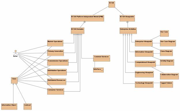
Figure 6: IntelliGrid Architecture Model – Key Concepts
Navigating IntelliGrid Architecture Model
The IntelliGrid Architecture model is organized hierarchy using a set of UML packages to provide separation of dividing concepts. The IntelliGrid Architecture package at the top level of the model is the parent for all the concepts modeled in IntelliGrid Architecture. Immediately under IntelliGrid Architecture package is a set of packages, dividing IntelliGrid Architecture into key concepts. Each of these key-dividing concepts outlined in this section are described in detail, in the later sections.
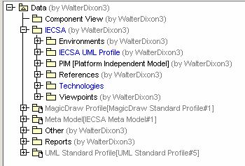
Figure 7:Top level package structure of
IntelliGrid Architecture Model
· Environments – Contains description of all IntelliGrid Architecture environments. Different aspects of IntelliGrid Architecture model will like to the corresponding environment.
· IntelliGrid Architecture UML Profile – Contains the set of UML extensions (stereotypes, tagged value definitions, and constraints) defined by IntelliGrid Architecture in order to convey key RM-ODP concepts as well as the definition of the key architectural issues the team solicited information on, from stakeholders during the stakeholder engagement process.
· PIM [Platform Independent Model] – Contains the set of information objects, actors that define the system. These objects are technology independent. The PIM package contains a child set of packages corresponding the six primary domains specified in IntelliGrid Architecture model.
These domains are represented by UML packages as shown in the following figure.
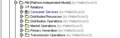
Figure 8: IntelliGrid Architecture Domains
· Technologies – Contains the set of technologies and their capabilities.
· Viewpoints – Contains the set of energy industry enterprise activities. The viewpoint package contains a child set of packages corresponding top-level enterprise activities. Each enterprise activity separates the modeling concepts into 5 child packages, one for each of the 5 RM-ODP viewpoints as shown in the following figure.
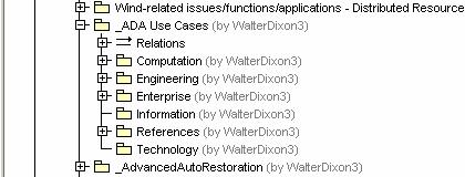
Figure 9: IntelliGrid Architecture Viewpoints Folder
Environments
An IntelliGrid Architecture Environment is defined as an environment where one or more of the information exchanges of Power System Operations functions have essentially the same architectural requirements, including their configuration requirements, quality of service requirements, security requirements, and data management requirements. The IntelliGrid Architecture Environments reflect the requirements of the information exchanges, not necessarily the location of the applications or databases (although these may affect the information exchanges and therefore the environment).
RM-ODP defines an Environment as the part of the model, which is not part of that object.[5]. This essentially represents external complexities in the model, and the classification of those complexities having similar requirements.
Figure 10: IntelliGrid Architecture Environments
For this RM-ODP concept – the UML collaboration is chosen, as shown in the figure above, to represent the abstract behavior construct conveyed by the external influences of the un-modeled elements of the environment. Additional details for UML Collaborations are shows in the table below.
|
Collaboration Additional Modeling Details |
|
|
Collaboration Name |
Corresponds to IntelliGrid Architecture Environment name. |
|
Collaboration Documentation Attribute |
Corresponds to the description of IntelliGrid Architecture Environment. |
|
Collaboration as a Tagged Value Reference |
The collaboration representing the environment may appear as a tagged value reference as a means of annotating which steps are part of which environment. |
IntelliGrid Architecture UML Profile
The formal notation of UML includes extension mechanisms (stereotypes, tagged value definitions, and constraints) that allow UML to expand its notational constructs beyond those identified in the UML standard. These extension mechanisms are critical to the adaptation of RM-ODP concepts.
Tagged Values
Tagged values are the primary extension mechanism used by IntelliGrid Architecture. Tagged values are used to capture the key architectural issues presented to stakeholders when developing the domain use cases. These tagged value definitions are categorized using UML packages as shown in the figure below.
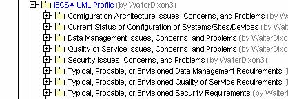
Figure 11: IntelliGrid Architecture Architectural Issues as
Tagged Value Definitions
Stereotypes
IntelliGrid Architecture uses stereotypes as a classification mechanism for the modeling elements defined through stakeholder engagement. A sample of the stereotypes are proved below:
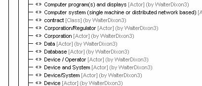
Figure 12: IntelliGrid Architecture Stereotypes
Constraints
IntelliGrid Architecture uses constraints to capture the invariant conditions supplied by stakeholders when developing the use cases. These constraints also include pre and post conditions for describing the various use case scenarios.
PIM [Platform Independent Model]
Using a technology independent design is an important concept when developing interoperable systems and equipment today. A technology independent design must focus on the behavior and structure of the components within a system and abstract the implementation details of any particular technology. This key concept allows for different implementations and technologies to exist, yet still allow these components to be used interchangeably. Using technology independent design enables a coherent architecture to be created independently of deployment specifics. When implemented, the technologies are chosen to meet requirements but are implemented in a way that complies with the technology independent design.
Domain
RM-ODP defines domain as “A set of objects, each of which is related by a characterizing relationship to a controlling object.”[5] These domains represent the primary division of the energy industry. It is convenient for the domain division to correspond to accepted industry practice, as it provides an immediate partition of the project into smaller areas of interest. However, in order for these systems to be integrated, there must exist components and services, which cross these domain boundaries, such as IntelliGrid Architecture Common Services.
· Market Operations
· Primary Generations
· Transmission Operations
· Distribution Operations
· Distributed Resources
· Consumer Services
· Common Services
Actors
RM-ODP and UML each define the concept of Actor. Essentially an actor is any object that plays a role in the system, meaning any object that can participate in an action. During the development of IntelliGrid Architecture use cases, a set of actors was developed. Examples of these actors include:
· RTOs/ISOs
· Generation Company
· Intelligent Equipment Device
|
Actors Additional Modeling Details |
|
|
Actor Name |
Corresponds to IntelliGrid Architecture Actor Name |
|
Actor Documentation Attribute |
Corresponds to the description of IntelliGrid Architecture Actor. |
|
Actor Stereotype Name |
The IntelliGrid Architecture actor type appears as a stereotype assigned to the actor. The stereotype is a means of classifying the actor. |
|
Actor Constraints |
The UML actor constraints correspond to IntelliGrid Architecture constraints. IntelliGrid Architecture constraint name maps to the UML constraint name. The IntelliGrid Architecture constraint description maps to the UML constrain expression (non-OCL). |
|
Actor Operations |
UML actor operations correspond to the “set” or “get” methods derived from IntelliGrid Architecture sequence of events. |
Based on the aggregate set of use cases developed for IntelliGrid Architecture, the actors developed a set of operations needing to support the detailed steps of the use cases. These operations
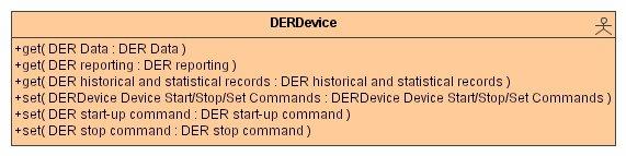
Figure 13: Actor Operations
Classes
Each domain except “Common Services” has a set of classes associated with it. These classes represent IntelliGrid Architecture information objects and/or IntelliGrid Architecture contracts/regulations.
An IntelliGrid Architecture information object maps to a UML class. An IntelliGrid Architecture contract / regulation maps to a class having the stereotype <<contract>>. The IntelliGrid Architecture policy maps to the operations of the <<contract>> class.
|
Classes Additional Modeling Details |
|
|
Class Name |
Corresponds to IntelliGrid Architecture information object name or the
contract / regulation name. |
|
Class Documentation Attribute |
Corresponds to IntelliGrid Architecture information object description or the contract / regulation description. |
|
Class Operations |
For the <<contract>> class, each policy associated with the contract is represented by an operation. The name of the operation is the policy name. The stereotype of the operation is corresponding to the policy type namely <<>> (for “May” type policy), <<prohibition>> (for “Shall Not” type policy) and <<obligation>> (for “Shall” type policy”). The operation documentation attribute corresponds to the policy description. |
|
Class Constraints |
The “Class constraints” correspond to IntelliGrid Architecture constraints. IntelliGrid Architecture constraint name maps to the UML constraint name. The IntelliGrid Architecture constraint description maps to the UML constrain expression (non-OCL). |
Figure 14: Example Class Operations (Contract)
Interfaces
“Common Services” domain contains a set of interfaces grouped by common service categories. There are four top-level categories of common services, namely, “data management”, “security management”, “network and system management” and “integration and federation”. The top-level categorizations are represented by UML package.
|
Interface Additional Modeling Details |
|
|
Interface Name |
UML “Interface name” corresponds to IntelliGrid Architecture interface
name, for example “DistributedDataManagementInterface”. |
|
Interface Documentation Attribute |
UML “Interface documentation attribute” corresponds to IntelliGrid Architecture interface description. |
|
Interface Operations |
UML “Interface operations” are IntelliGrid Architecture interface methods. The IntelliGrid Architecture uses the standard verbs such as: · get · create · change · cancel · close · delete · created · changed · closed · canceled · show · subscribe · unsubscribe |
|
Interface Constraints |
The “Interface constraints” correspond to IntelliGrid Architecture constraints. IntelliGrid Architecture constraint name maps to the UML constraint name. The IntelliGrid Architecture constraint description maps to the UML constrain expression (non-OCL). |
Viewpoints
The IntelliGrid Architecture has the five RM-ODP viewpoints, namely “enterprise viewpoint”, “information viewpoint”, “computational viewpoint”, “engineering viewpoint” and “technology viewpoint”. The basic constructs of these viewpoints are UML use case, use case diagram, class diagram, activity diagram, and collaboration diagram. Different from IntelliGrid Architecture model, IntelliGrid Architecture views are organized by enterprise activities and each enterprise activity has five viewpoints. For example, “Advanced Auto Restoration” is an enterprise activity.
Enterprise Viewpoint
The enterprise viewpoint is concerned with the purpose, scope, and policies of the enterprise related to IntelliGrid Architecture. An enterprise specification of a service is a model of the service and the environment with which IntelliGrid Architecture interacts. It covers the role of IntelliGrid Architecture in the business as well as the human user roles and business policies related to IntelliGrid Architecture. The Enterprise viewpoint is defined by a set of use cases, collaborations, use cases diagrams and class diagrams.
Use Case
The IntelliGrid Architecture enterprise activity is represented by the UML use case in the MagicDrawÔ. Enterprise activity contains a set of sub-activities and services, which are also represented by UML use cases.
|
Use Case Additional Modeling Details |
|
|
Use Case Name |
A use case will have a name that is corresponding to the
enterprise activity name. |
|
Use Case Documentation Attribute |
A use case will have documentation attribute which contains the description of the enterprise activity. |
|
Use Case Tagged Value |
The use case of IntelliGrid Architecture enterprise activity will have a tagged value that specifies IntelliGrid Architecture function identification number (function id). The IntelliGrid Architecture function id is a unique identifier of a specific IntelliGrid Architecture function. The id contains a letter that is assigned to each domain and a set of numbers delimitated by “.” to show the hierarchy of the functions. For example, T-1.1 is the id for the “long term load forecast” function in the transmission operation domain. An enterprise activity could have more than one function id. For example, the function id for “Advanced Auto-Restoration” are >>>>. The purpose of capturing the function id is to maintain the traceability of IntelliGrid Architecture view to the requirements. |
Use Case Diagram
IntelliGrid Architecture includes two concepts in use case diagrams. To convey organization and hierarchy, a use case diagram will show the relationship between a high-level use case, and lower level use cases. For example:
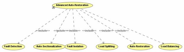
Figure 15: Use Case Hierarchy
As shown in the Figure
15: Use Case Hierarchy the Advance Auto-Restoration use case – includes a
number of subordinate use cases. The
subordinate use cases are linked through an “<<include>>”
dependency.
The second concept modeled in IntelliGrid Architecture use cases is that of actor involvement.

Figure 16: Example Use Case
The Figure 16: Example Use Case diagram shows the set of actors directly involved in the Advanced Auto-Restoration use case.
Collaboration
RM-ODP defines Community as “a configuration of objects formed to meet an objective. The objective is expressed as a contract that specifies how the objective can be met.” [5]. This concept maps well to the UML Collaboration, which is defined as an abstract structuring concept. The members of the collaboration represent cooperative elements that come together to meet a specific objective.

Figure 17: Example Community
Membership in the community is defined by the set of UML Role Classifiers owned by the community. The role Classifier has a base classifier set to the corresponding actor.
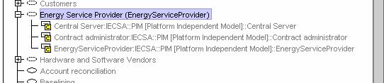
Figure 18: Example Community Membership
|
Collaboration - Additional Modeling Details |
|
|
Collaboration Name |
Corresponds to IntelliGrid Architecture Grouping (Community) name. |
|
Collaboration Documentation Attribute |
Corresponds to IntelliGrid Architecture Grouping (Community) description. |
|
Owned Elements |
Membership defined through the set of owned Classifier Roles. |
Class Diagram
The class diagram is used to expose the contractual bindings of the actors. A UML class represents IntelliGrid Architecture contract/regulation and IntelliGrid Architecture policies are represented by the operations in the class.
Figure 19: Contract Governing Actors
As shown in the figure, the two actors are associated with each other with a contract called “Competition between neighboring utilities” binding the interface. The binding is shown by the UML “permission” association.
Information Viewpoint
The information viewpoint is concerned with the semantics of information and information processing. The information specification of IntelliGrid Architecture is a model of the information objects that the system holds and the governing states of the system. The information viewpoint is defined by a set of information objects (classes), activity diagrams conveying system state and class denoting static structuring concepts.
Activity Diagram
The activity diagram is used to describe IntelliGrid Architecture enterprise activity sequence of event together with the collaboration diagram. The IntelliGrid Architecture sequence number maps to the UML transition name attribute. The IntelliGrid Architecture event maps to the guard condition expression o the transition. The name of the process / activity maps to the UML “action state”. The “description of process / activity” maps to the action state documentation attribute. The “name of info exchange” maps to the “Object Flow State”.
Figure 20: Activity Diagram (part-of)
Computational Viewpoint
The computational viewpoint is concerned with the
interaction patterns between the components (services) of IntelliGrid Architecture, described
through their interfaces. A
computational specification of a service is a model of the service interfaces
seen from a client, and the potential set of other services required by that
service. The computational model defines
types of interfaces such as request/reply or publish/subscribe or whether an
interface is designed for exchange of real time or historical data. For example,
interfaces may be defined as API’s such as CCAPI’s Generic Interface Definition
or as a wire protocol such as UCAÒ’s[PCAS1]
device oriented services.
Computational Viewpoint is represented by UML collaboration and activity
diagrams.
Collaboration Diagram
The collaboration diagram is used to describe IntelliGrid Architecture enterprise activity sequence of events. The role classifier of the collaboration diagram corresponds to IntelliGrid Architecture “information producer” and “information receiver” with the existing actors as their base classes.

Figure 21: Collaboration Diagram
(part-of)
1.1.1.1.1 Message
The message “Action type” is set to be “call” action having the name of IntelliGrid Architecture “name of process/activity”. The “call” action documentation attribute corresponds to IntelliGrid Architecture “description of process/activity”.
Engineering Viewpoint
The engineering viewpoint is concerned with the design of heterogeneous aspects, of the information infrastructure required to support distributed systems. The engineering viewpoint is the least defined viewpoint of IntelliGrid Architecture, since this viewpoint is closer to the implementation details than current project scope permitted to define. The current IntelliGrid Architecture engineering viewpoint includes a set of diagrams collected during the stakeholder engagements. Future work, perhaps confined to specific projects using IntelliGrid Architecture, shall develop this viewpoint.
Technology Viewpoint
The technology viewpoint is concerned with the provision of an underlying technology infrastructure, consisting of a set of technology related capabilities and recommendations. The technology viewpoint, like the engineering viewpoint, is closer to the implementation details than current project scope permitted to define, however, significant technology related details are presented through a set of class definitions. These classes are annotated with a set of UML tagged values, expressing the technology capabilities.
This page intentionally left blank.
References
[1] Booch, Jacobson, Rumbaugh; The Unified Modeling Language User Guide, Addison-Wesley, 2001
[2] Enterprise Architecture Methods & Approaches, http://www.enterprise-architecture.info/Architecture_Methods.htm
[3] Janis R. Putman, Architecting with RM-ODP, Prentice Hall PTR, 2001.
[4]
OMG, Relationship of the Unified Modeling Language
to the Reference Model of Open Distributed Computing, OMG, version 1.4,
[9] What is Systems Engineering, http://www.incose.org/whatis.html
[10] John Oldevik, RM-ODP Overview, www.informatics.sintef.no
[11] Andrey Naumenko, Formalization of RM-ODP: Object-Oriented Ontology for System Modeling, Swiss Federal Institute of Technology, Lausanne (EPFL), Institute for computer Communications and Applications (ICA)
[12] Frederick P. Brooks, Jr., Mythical Man-Month: The Essays on Software Engineering, University of North Carolina at Chapel Hill, Anniversary Edition, 2/E”1, 1995
[13]
Scott W. Ambler, Bringing data professionals and
application developers together, http://www.ronin-intl.com/company/scottAmbler.html
[14] Kruchten 2000; Ambler 2001b,Unified Process, http://www.ronin-intl.com/publications/unifiedProcess.html
[15] Scott W. Ambler, Agile Enterprise Architecture: Beyond Enterprise Data Modeling, http://www.agiledata.org/essays/enterpriseArchitecture.html
[16] IEC TC 57 WG 14, 61968 System Interfaces For Distribution Management Part 1: Interface Architecture and General Requirements
[17] Mohamed Mancona Kandé, Shahrzade Mazaher, Ognjen Prnjat, Lionel Sacks, Marcus Wittig, Applying UML to Design an Inter-Domain Service Management Application, [Available online] http://www.db.informatik.uni-bremen.de/umlbib/authors/WittigMarcus.html, UML'98: Beyond the Notation - International Workshop (Final Proceedings), 1998, (BibTeX entry).
[18] Guy Genilloud, Alain Wegmann, Role is an <X>:a Foundation for the Concept of Role, May 2000.
[19] Marie-Pierre Gervais, ODAC : An Agent-Oriented Methodology Based on ODP, Accepted for publication in Journal of Autonomous Agents and Multi-Agent Systems, Jan. 2002
[20] OMG, Unified Modeling Language Specification, Version 1.4 – 200
[PCAS1]Legal check Use capital letters to identify as TM don’t use TM or Regitered Mark unless you know for certain.